Last modified:
Note
The content on this page refers only to the blue'Log XC combined with the Hybrid EMS licence.
About frequency control
All countries have a standard grid frequency, for example, 50 Hz in Europe, and it is essential to maintain the frequency to prevent blackouts and damage. The grid code of each country requires power-generating systems to apply frequency control during inadmissible system frequency changes. Depending on the requirements, this can be carried out by the inverters or a power plant controller such as the blue’Log XC.
The blue’Log XC allows you to regulate the frequency-dependent active power output in three different modes:
Each of the control modes can be individually configured for the PV system as well as for the battery system.
Prerequisites
-
Hybrid EMS license
-
Only the user group Service can make changes. See Users.
-
Meter/power analyzer is compatible with blue'Log. See Compatibility Check.
-
Meter/power analyzer fulfills the measurement requirements for frequency control.
Example: Your grid code requires the frequency to be measured with a certain accuracy. -
For configuration assistance, we recommend our project-specific controller tuning services. For more information, see Project-specific controller tuning blue'Log XC and contact Sales.
Required measured values
In order to perform frequency control properly, measurements of active power and frequency are required. You can configure the source of both values.
Note
The frequency control behaves differently depending on the plant configuration:
-
PV or battery standalone: The frequency control setpoint is processed in closed-loop on the measured active power value of the configured feed-in meter. See Plant data (Hybrid EMS).
-
Hybrid plant: The individual frequency control setpoints of the PV and the battery plant are processed in open-loop at the individual inverter level.
Limited frequency sensitive mode - underfrequency (LFSM-U)
Underfrequency occurs when the frequency of the electrical grid falls below the nominal operating frequency. A deficit of generation power is opposed to a surplus of load. To correct this, the active power output of the system is increased according to a characteristic curve P(f) until the grid frequency returns to the permissible range.
The following parameters can be configured:
|
Parameter |
Description |
|
|---|---|---|
|
1 |
Frequency bands |
You can configure up to five frequency bands. For each frequency band, you can set a dedicated droop and frequency threshold. |
|
2 |
Reset frequency freset |
Frequency above which LFSM-U is deactivated. |
|
3 |
Frequency threshold fthd |
Frequency below which LFSM-U is activated. |
|
4 |
Minimum system frequency fmin |
Frequency below which the active power output is not further increased. |
|
5 |
Droop sf |
Ratio of the steady-state change of frequency Δf to the resulting steady-state change in active power output ΔP. |
|
6 |
Reference active power Pref |
Power to which the calculated active power change ΔP refers:
|
Limited frequency sensitive mode - overfrequency (LFSM-O)
Overfrequency occurs when the frequency of the electrical grid exceeds the nominal operating frequency. To correct this, the active power output of the system is limited according to a characteristic curve P(f) until the system frequency returns to the permissible range.
You can configure the following parameters:
|
Parameter |
Description |
|
|---|---|---|
|
1 |
Frequency bands |
You can configure up to five frequency bands. For each frequency band, you can set a dedicated droop and frequency threshold. |
|
2 |
Reset frequency freset |
Frequency below which LFSM-O is deactivated. |
|
3 |
Frequency threshold fthd |
Frequency above which LFSM-O is activated. |
|
4 |
Minimum system frequency fmax |
Frequency above which the active power output is not further decreased. |
|
5 |
Droop sf |
Ratio of the steady-state change of frequency Δf to the resulting steady-state change in active power output ΔP. |
|
6 |
Reference active power Pref |
Power to which the calculated active power change ΔP refers:
|
Frequency sensitive mode (FSM)
In this mode, the active power is adjusted according to a defined P(f) curve to provide the ancillary service frequency containment reserves (FCR, also known as primary control reserves). Thus, FSM is only relevant if your system participates in the electricity balancing market. Compared to the LFSM-O and LFSM-U modes, FSM mode is usually active during smaller frequency deviations. In case of overlap, LFSM-O and LFSM-U have priority over FSM.
|
Parameter |
Description |
|
|---|---|---|
|
1 |
Insensitivity ΔfIS |
During frequency changes smaller than the configured insensitivity, the controller will not generate a new setpoint. This serves to avoid unnecessary control activity in the event of small frequency fluctuations. |
|
2 |
Active power range |ΔP1/Pinst| |
Indicates the maximum amount by which the active power can be increased or reduced by the FSM function. If the active power was increased or reduced by |ΔP1/Pinst|, no further active power adjustment takes place even if the grid frequency continues to decrease or increase. Exception: When LFSM-O/LFSM-U are activated, these functions may further decrease/increase active power output. |
|
3 |
Deadband ΔfDB |
Is centered around the nominal frequency fn. As long as the system frequency f remains within the frequency range (fn - ΔfDB) < f < (fn+ΔfDB), there is no frequency-dependent active
|
|
4 |
Base value Pbase |
The power change ΔP resulting from the P(f) characteristic curve is added to the base value to obtain the resulting active power setpoint.
*The remote power control setpoint PRPC is the setpoint transmitted via the Remote Power Control (RPC) interface for the respective system (PV or battery). This option is only available if the Remote Power Control (RPC) license is installed. |
|
5 |
Droop sf |
Ratio of the steady-state change of frequency Δf to the resulting steady-state change in active power output ΔP. |
|
6 |
Reference active power Pref |
Power to which the calculated active power change ΔP refers:
|
Note
By default, the P(f) characteristic curve is set up symmetrically.
To configure the parameters (|ΔP1/Pinst|,sf and ΔfDB ) separately for underfrequency and overfrequency, activate the toggle Asymmetric characteristic curve.
FSM commands via Modbus
The energy trader can activate FSM and set the active power range via Modbus. For this, consider the following:
-
The Modbus Power Control license is required.
-
Refer to the data sheet for the relevant registers.
-
You must first activate the parameters via the blue’Log user interface: Power control > Active power > Frequency control > Active power adjustment P(f) - FSM > Activate FSM via Modbus toggle.
Set a ramp rate limiter (after frequency restoration)
If the frequency event ends and the frequency is restored, a ramp rate limiter can be applied to the transition to normal operation.
This function applies only after LFSM-U and LFSM-O events and cannot be set if FSM is activated.
Example
The power was reduced to 500 kW during the frequency event, but the plant can deliver 800 kW after the frequency event ends, and no power limitations are present. In this scenario, if the ramp rate limiter is activated after frequency restoration, the power does not immediately return to maximum power (800 kW) but has a configurable rate of change.
Calculation of the active setpoint
During frequency control, the blue’Log XC monitors the frequency and calculates the
active power change according to the following formula:
ΔP/Pref = (fthd - fmeasured) / (fn * sf)
-
ΔP calculated absolute active power change (W)
-
Pref active power reference (W)
-
fthd frequency threshold from that on frequency control is activated (Hz)
-
fmeasured measured system frequency (Hz)
-
fn nominal system frequency (Hz)
-
sf droop (%)
Note
In FSM mode, the frequency threshold fthd is calculated by the sum of the nominal frequency fn and the frequency deadband ΔfDB: fthd = fn+ Δ𝑓𝐷𝐵
The calculated active power change is added to the base active power 𝑃𝑏𝑎𝑠𝑒 to obtain the final
setpoint during frequency control:
Psetpoint = Pbase + ΔP
Note
For LFSM-U and LFSM-O, the base value Pbase corresponds to the momentary active power Pmom when the frequency threshold is exceeded. For FSM, the base value is alternatively configurable as the remote power control setpoint from the energy trader.
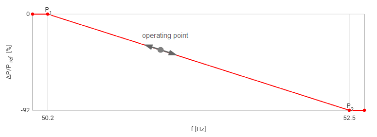
The frequency-dependent power output (operating point) permanently moves up and down along the configured P(f) characteristic curve depending on the measured grid frequency (see figure below):
Ignore grid operator command
By default, the grid operator can limit the plant's power also during a frequency event. If this is not desired and the grid operator is unable to limit power during frequency events, you can activate the function Ignore grid operator command. In this case, the plant’s power always follows the defined P(f) characteristic curve.
Configure this function for each frequency control mode (LFSM-O, LFSM-U, FSM) under Power Control > Active power > LFSM-U/LFSM-O/FSM > Options.
Note
The function Ignore grid operator command only refers to the limitations at the plant level (limitation of PV power, limitation of charge/discharge power). The feed-in and import limitation set by the grid operator always has priority over the P(f) function.
Example
The energy trader curtails the PV system to 0% due to negative electricity prices. Because an underfrequency event occurs, LFSM-U is activated, and the power increases to 5%.
-
By default, the grid operator can curtail the power again, e.g. to 0%.
-
If Ignore grid operator command is activated, the grid operator commands are ignored. The PV system continues to operate at 5% in accordance with the P(f) curve.