Last review:
About power control and digital inputs
Digital inputs are one method of active power control. This often involves a (radio) ripple control receiver, for example. The following example illustrates the connection and configuration of a ripple control receiver using digital inputs.
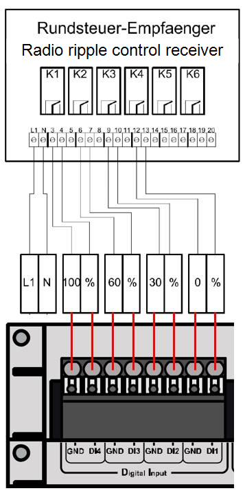
A radio ripple control receiver with 4 potential-free normally open contacts (NO) should regulate the active power of the system in the following stages:
-
100%
-
60%
-
30%
-
0%
Wire a ripple control receiver to the blue'Log
The 4 potential-free normally open contacts are connected to the 4 digital (DI 1-4) inputs of the blue'Log.
Configure active power control on the blue'Log
-
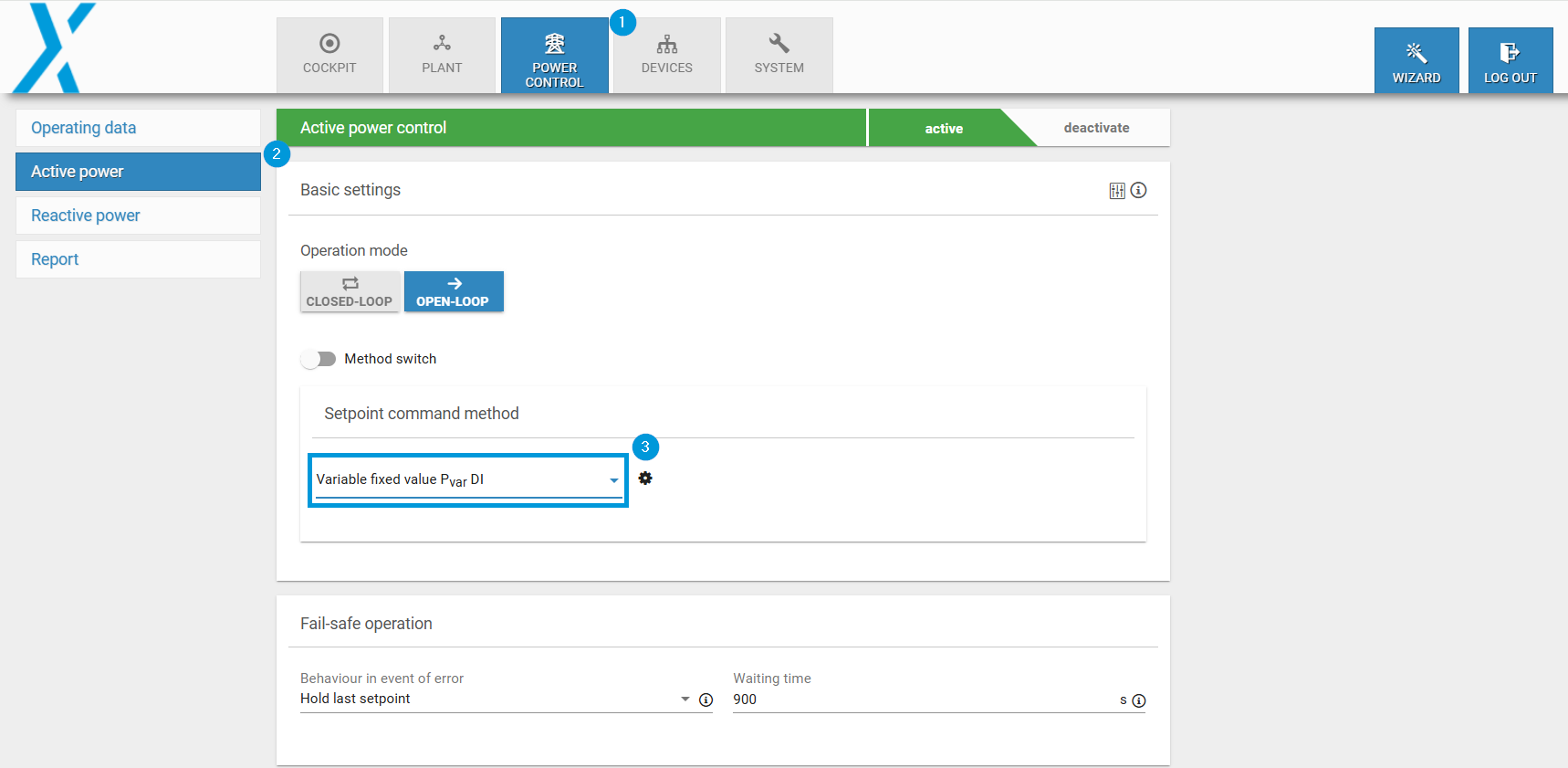
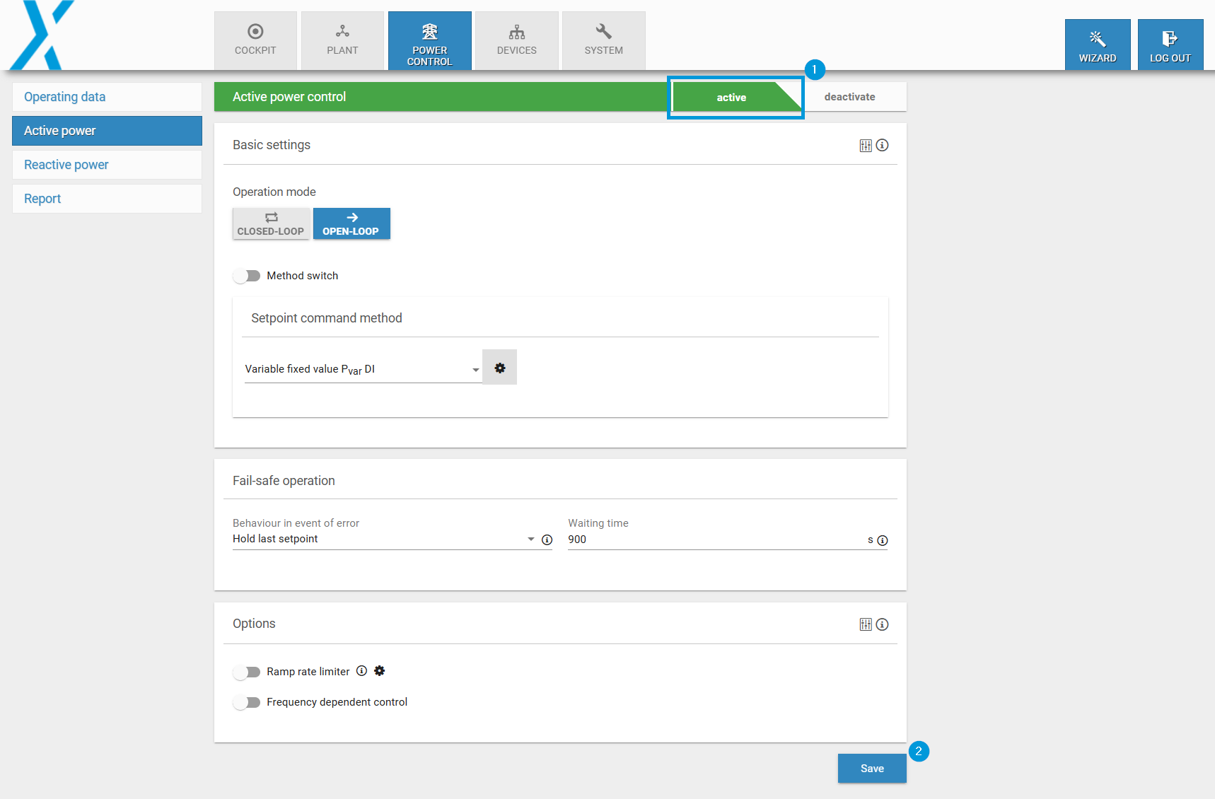
On the blue'Log web interface, go to Power Control > Active Power > Basic Settings.
-
Select the setpoint command method Pvar DI. A window appears.
Define the interface
-
Pulse group: Here you can specify whether the inputs are switched as pulses or permanently. You can find this information in the manufacturer's documentation for the ripple control receiver.
-
Input (command): Specify the inputs required for control. By default, all 4 digital inputs are listed. If you need fewer than 4 inputs, remove them via the

-
Acknowledgment: Some network operators require an acknowledgment of the input signals. For this, activate the Acknowledgment toggle. By default, the acknowledgments are output at the 4 digital outputs (DO 1-4) of the blue'Log. Advanced configuration options are available for this.
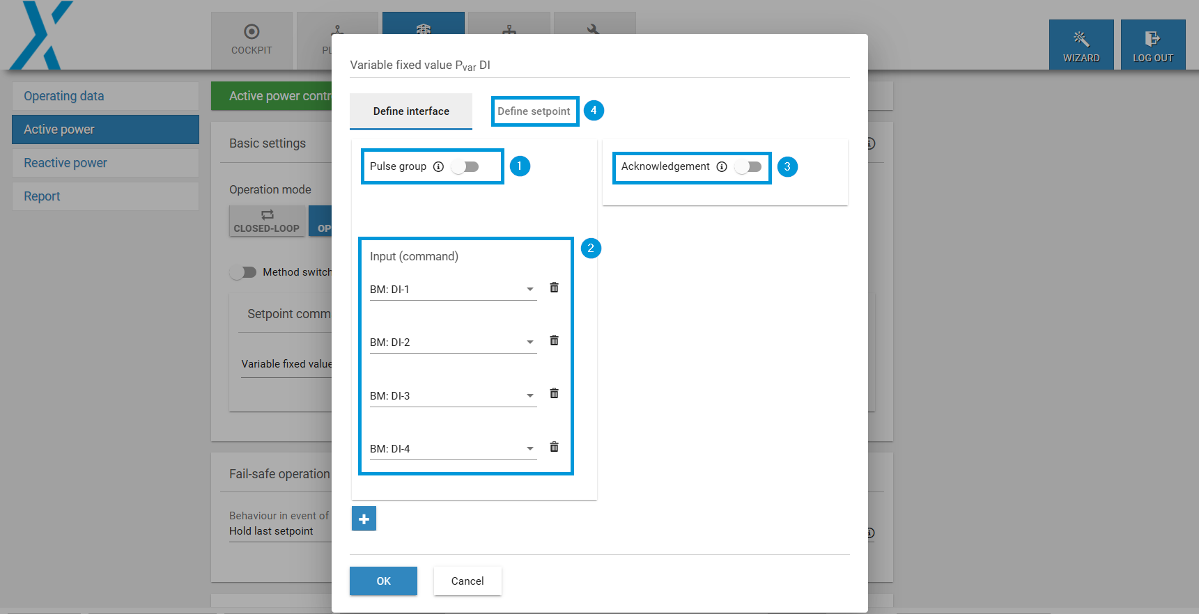
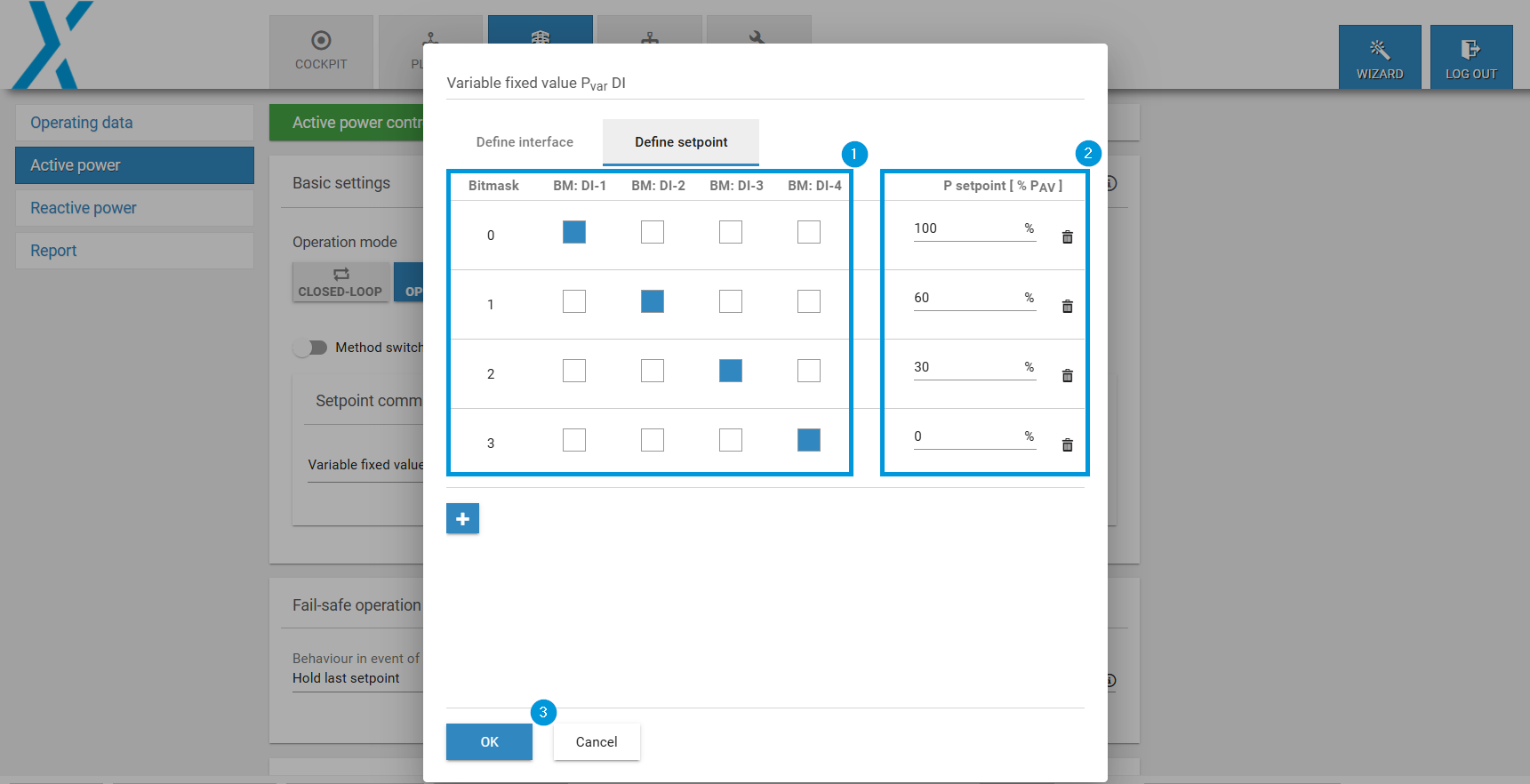
Define the setpoint
-
Select the Define setpoint tab.
-
Set the inputs according to their assignment.
-
Assign a corresponding setpoint to each input.
-
Select OK.
-
The setup is complete.
Next steps
After configuration is completed, be sure to:
-
Activate the Power Control toggle.
-
Select Save.
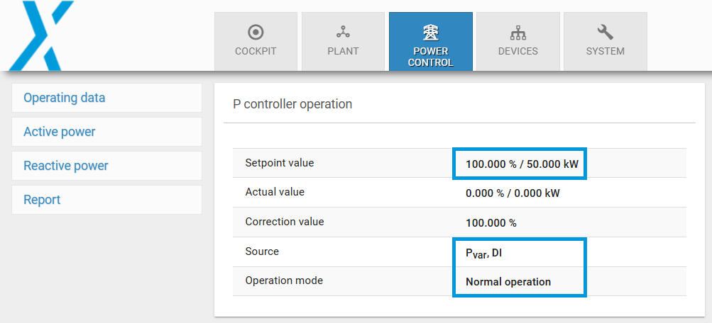
Check that the inputs are working properly
You can also simulate this step by bridging the corresponding inputs (DI 1-4) with GND. Check if the corresponding setpoint value is used under Power Control.