Last modified:
Note
The content on this page refers only to the blue'Log XC combined with the Hybrid EMS licence.
About energy management
The blue’Log offers different operation modes. Those operation modes define the base behaviour of the system. This behaviour can be influenced by all grid security relevant features like power limitations at the grid connection point, frequency control, grid operator and also trader commands. Those operation modes comprise energy management functions like PV self-consumption and band shaving to allow plant operators, especially in combination of PV and battery systems, to operate their systems as efficiently as possible.
You can set the following operation modes under Power Control > Active power > Energy management. The available operation modes depend on the plant type you have configured under Plant data (Hybrid EMS).
|
Operation mode |
Plant type |
|
|---|---|---|
|
1 |
Setpoint command (inverter) |
|
|
2 |
Setpoint command (GCP) |
|
|
3 |
PV self-consumption |
|
|
4 |
Band shaving |
|
Setpoint command (inverter)
In Setpoint command (inverter) mode, the blue’Log relies on external commands from the energy trader (via the Remote Power Control interface). The plant-specific setpoints are implemented at the inverter level. Loads and self-consumption are not compensated. Additionally, the active power at the grid connection point (GCP) can be limited by the trader. The following commands can be sent:
-
Active power setpoint PV → applies at PV inverter level
-
Active power setpoint battery → applies at battery inverter level
-
Active power feed-in limitation at GCP → curtails power at the grid connection point
All commands can be sent simultaneously. For the individual registers, refer to Remote Power Control license (RPC) blue'Log XC data sheet.
As long as the energy trader does not send any signals, the PV system is not limited (Psetpoint,PV = 100%), and the battery system neither charges nor discharges (Psetpoint,battery = 0%).
Use case
Setpoint command (inverter) mode is primarily used for hybrid systems when the energy trader controls the systems individually to participate in energy markets such as:
-
Intraday/day-ahead markets.
-
Balancing services markets: Frequency Containment Reserves (FCR) or Frequency Restoration Reserves (FRR).
For standalone systems and control commands at the grid connection point, refer to Setpoint command (GCP) mode.
Setpoint command (GCP)
In Setpoint command (GCP) mode, the blue’Log relies on external commands from the energy trader (via the Remote Power Control interface). The plant-specific setpoints are implemented at the grid connection point (GCP). Loads and self-consumption are compensated. This mode is only available for standalone systems (PV or battery standalone).
-
Active power setpoint PV → applies at the grid connection point
-
Active power setpoint battery → applies at the grid connection point
-
Active power feed-in limitation at GCP → not applicable
For the individual registers, refer to Remote Power Control license (RPC) blue'Log XC data sheet.
As long as the energy trader does not send any signals, the PV system is not limited (Psetpoint,PV = 100%), and the battery system neither charges nor discharges (Psetpoint,battery = 0%).
Use case
Setpoint command (GCP) mode is only used for standalone systems when the energy trader controls the system to participate in energy markets such as:
-
Intraday/day-ahead markets.
-
Balancing services markets: Frequency Containment Reserves (FCR) or Frequency Restoration Reserves (FRR).
PV self-consumption
In PV self-consumption mode, the hybrid system is controlled such that all available solar power is used for self-consumption to cover the local load. Any excess solar energy is used to charge the battery. PV Power is only fed into the grid when the battery is fully charged and the load is covered. If solar energy generation is not sufficient to cover the local load, the battery discharges the stored energy. In this mode, the PV system is never curtailed.
Example
This example shows a plant setup with a PV system (10 MW), a battery system (5 MW), and a connected load. In this chart, the load varies in order to illustrate the behavior of the operation mode.
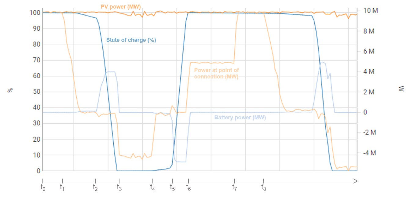
t0 - t1: No load is present and the battery is fully charged. All available PV power is fed into the grid.
t1 - t2: The load increases, but can still be covered by the PV system. The battery’s SOC remains stable.
t2 - t3: The load exceeds the available PV power. The battery starts discharging to compensate for the missing PV power so that no power must be drawn from the grid.
t3 - t4: The battery is entirely discharged (SOC=0%) and the PV system is no longer able to cover the local consumption. Thus, power is drawn from the grid.
t4 - t5: The load reduces and the PV plant can cover local consumption again (no consumption from the grid).
t5 - t6: The load further decreases. Excess PV power is available to charge the battery.
t6 - t7: The battery is fully charged again. The PV power covers the local load. The excess PV power is fed into the grid.
t7 - t8: No load is present and the battery is fully charged. All available PV power is fed into the grid.
Band shaving
The goal of Band Shaving mode is to maintain the power exchange at the grid connection point — both feed-in and import — within a specified range. This range is defined by two power thresholds which can be configured:
-
Lower limit
-
Upper limit
The system operates such that the power at the grid connection point remains below the upper limit and above the lower limit.
The upper limit triggers the battery to charge or the PV system to be curtailed:
-
When the power at the grid connection point reaches the upper limit, the battery begins to charge in order to absorb the excess energy and maintain the power at the grid connection point below the upper limit.
-
If the battery is already full or cannot absorb all the surplus power, the PV system is curtailed to prevent exceeding the upper limit.
Conversely, the lower limit triggers the battery to discharge:
-
When the power at the grid connection point drops to the lower limit, the battery starts discharging to ensure the power at the grid connection point does not fall below the lower limit.
Info
The upper limit currently triggers both battery charging and PV curtailment with a single threshold value. This will be split in a future release:
-
Upper limit (Battery): Defines the threshold at which the battery begins charging.
-
Upper limit (PV): Defines the threshold at which PV curtailment is triggered.