Last modified:
See also Virtual system.
Note
Currently, it is not possible to create virtual systems including batteries. So the following steps only apply to systems that virtualize source systems without batteries.
Recommendation
Since you will probably need to reference or copy a lot of data from source systems, we recommend opening two VCOM sessions: One for the source system(s), and one for the virtual system. This works best if you open and sign in to VCOM in two different browsers, for example, Chrome and Firefox, and arrange the windows side-by-side.
Find the configuration workflow at the virtual system’s system level > ![]()
![]()
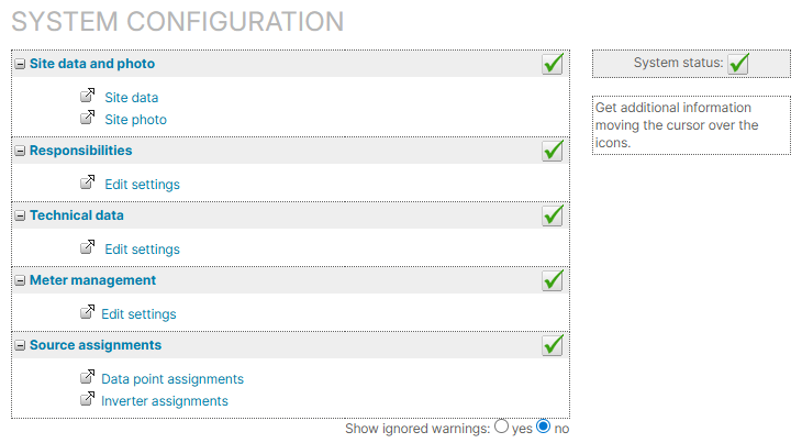
Site data and photo
Site data
If you just set up the new system, you already entered its site data, and you do not have to do anything else here. See also Site data.
Site photo
If a ![]()
Responsibilities
Most of the responsibilities do not apply to virtual systems, so it is not necessary to assign a user to them. However, you can assign responsibilities for informational purposes, see Responsibilities.
Technical data
If there is ![]()
![]()
You must recreate all subsystems of the source systems you want to virtualize. See Subsystems.
Note on navigation
Only setting up subsystems via the updated Technical data page is described in this Help Center. But the link in the list does not yet redirect to this new page. Therefore, go directly to Technical data in the side menu. On this page you will find the Subsystems area.
Support
If you would have to recreate more than 20 subsystems, you can send a support request for further assistance.
Meter management
When setting up the basic framework for your system, a meter of the type Solar energy meter is automatically added to your system, and you can edit its settings. See Meter.
If ![]()
Source assignments
Data point assignments
![]()
![]()
![]()
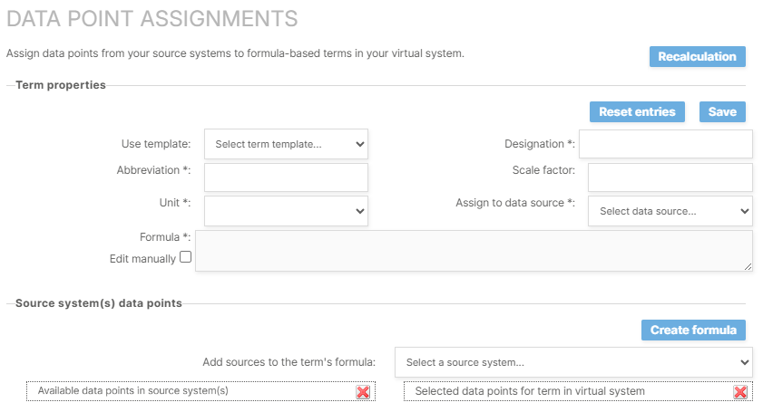
Create terms one after the other for data points you want to monitor in your virtual system.
Steps-
Define Term properties:
-
In the area Term properties, enter the term’s Designation, Abbreviation, and Unit. See Define term properties for more information on these three properties.
-
The Scale factor is only needed for terms with the unit kWh. It is also not needed if you are defining the overall generated energy
E_Z_EVU. You must only enter it if you are creating a term for a subsystem’s actual energy in order to facilitate comparisons with other subsystems or overall meters. As a rule, it refers to the nominal power of a system/subsystem in kWh. -
For Assign to data source, select the Calculated values option as container in which the term data is to be stored.
-
The Formula is defined in the second step below.
-
You must at least create a term for the actual generated energy
E_Z_EVU. If the irradiance on module plane/POAIG_M0is also defined in all your source systems, create it here as well. Start to define these terms by selecting them from the dropdown Use template. Designation, abbreviation, and unit are pre-defined for these terms, and you do not have to enter them separately.
-
-
Select the source system(s)’ data points for the Formula:
-
Under Source system(s) data points > Add sources to the term's formula, your entire portfolio’s systems are listed in the dropdown.
-
Select the (first) source system that is part of the virtual system.
-
All measured and calculated data points of that system that are available for term creation are now listed on the left side under Available data points in source system(s) grouped by that system’s data sources serial number/SN. Calculated values are grouped in their own data source with their own software serial number/SN.
-
Depending on the term you are creating at the moment, you must choose the right data points to be included in its formula. Drag and drop each desired data point one-by-one from the list on the left to the list Selected data points for term in virtual system on the right. To do this, select a data point with the left mouse button, keep holding down the mouse button, drag the mouse to the right side, right under the list’s headline (until a transparent rectangle appears), and release the mouse button. If the list on the left is very long and you want to drag and drop a data point from the bottom of the list, you must additionally scroll your mouse wheel up while holding the left mouse button to reach the right place to drop the item. Otherwise, no data point is added to the list on the right. If you mistakenly added a data point, remove it by selecting

-
If you want to combine systems, you can also select another source system from the dropdown Add sources to the term’s formula. This will again add the available data points of that system to the top of the list on the left. Since the list will get very long, the more source systems you select, and therefore, the dragging and dropping becomes more complicated, we recommend to
-
Repeat these steps for all data points you want to include in the new term’s formula.
-
Recommendation
In a second browser window, you can also refer to the source system’s list of terms or the ![]()
![]()
![]()
-
Now that you have selected all the data points, you can create the formula for the virtual system’s new term:
-
Select Create formula.
-
The data points are now added to the Formula in the area Term properties.
-
Usually, the data points are aggregated as
sum. If you want to aggregate the values as average, tick the formula’s checkbox Edit manually and change the aggregation toavg, for example, for the irradiance on module plane. Refer to our Term documentation or the Formulas section for more formula options.
-
-
Select Save to save the term.
Results
-
The term is now added to the list Available terms in the area Already configured terms.
-
The data points created with the new term can be monitored at system level in the Evaluation tab, or you can use them in user-defined charts, see Manage user-defined charts at system level.
-
In the System configuration overview, under Source assignments, the new page link Inverter assignments is available. See detailed steps below.
Example
Use case: You combined two physical systems to one virtual system. Now you want to monitor the overall Actual energy.
Procedure:
-
In the virtual system, create a new term
E_Z_EVU. Assign this term to the data source container Calculated values (SN333333). -
For the formula, select the respective
E_Z_EVUterms of the source systems, for example,E_Z_EVU(SN111111)andE_Z_EVU(SN222222). -
After creating the formula, the virtual system’s actual energy will be calculated as the following sum:
'E_Z_EVU(SN333333)' = sum('E_Z_EVU(SN111111)';'E_Z_EVU(SN222222)')
-
Select Recalculate to recalculate the term’s values for a selected period.
-
Create more terms in the same manner for data points you want to monitor in the virtual system, for example, Self-consumed energy
M_AC_E_OWN, global horizontal irradianceG_H0, or average module temperateT_M0. -
Select an already configured term from the dropdown Available terms to edit its properties later. Additionally, select Delete to delete the whole term for the virtual system. This has no effect on data points or terms in the corresponding source systems.
Inverter assignments
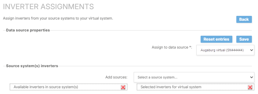
In order to display correct inverter data, you must assign the inverters of your source system(s) to the virtual system. No separate terms are necessary for this.
Prerequisites-
You have made data point assignments. See previous section.
-
At system level , go to


Inverter assignments for virtual systems -
For Assign to data source, select the [Name of the current virtual system] option as container in which the inverter data is to be stored.
-
Select the source system(s)’ inverters:
-
In the area Source system’s inverters > Add sources, your entire portfolio’s systems are listed in the dropdown.
-
Select the (first) source system that is part of the virtual system.
-
All inverters of that system are now listed on the left side under Available inverters for source system(s) grouped by that system’s data sources serial number/SN.
-
Drag and drop each desired inverter one-by-one from the list on the left to the list Selected inverters for virtual system on the right. To do this, select an inverter with the left mouse button, keep holding down the mouse button, drag the mouse to the right side, right under the list’s headline (until a transparent rectangle appears), and release the mouse button. If the list on the left is very long and you want to drag and drop an inverter from the bottom of the list, you must additionally scroll your mouse wheel up while holding the left mouse button to reach the right place to drop the item. Otherwise, no inverter is added to the list on the right. If you mistakenly added an inverter, remove it by selecting
-
If you want to combine systems, you can also select another source system from the dropdown Add sources. This will again add the available inverters of that system to the top of the list on the left. Since the list will get very long, the more source systems you select, and therefore, the dragging and dropping becomes more complicated, we recommend to
-
Repeat these steps for all inverters you want to include in your virtual system.
-
Recommendation
In a second browser window, you can also refer to the source system’s Data logger overview at system level > ![]()
![]()
-
Select Save to save the inverter assignments.
Results
-
The inverters are now added to the list Available inverters in the area Already assigned inverters.
-
Inverter charts are now visible at system level in the Evaluation tab.
-
Inverters are now available to be assigned in the System profile.
-
Select an already assigned inverter from the dropdown Available inverters to change its name. This is useful for differentiation if you assigned two inverters with the same name, but from two different source systems.
-
Additionally, select Delete to revoke the assignment of the inverter to the virtual system. This has no effect on the inverter in the corresponding source system.
Configure system profile
Although it is not separately listed in the configuration workflow, configuring a system profile is mandatory for virtual system. By doing so, you connect the theoretical inverter framework of the subsystems with the actual inverters you assigned to the virtual system in the previous step.
Prerequisites-
You recreated all subsystems of the source system(s) in your the virtual system.
-
You assigned the inverters of the source system(s) to the virtual system.
-
At the virtual system’s system level , go to
-
In the left column, select the first subsystem.
-
In the right column, select

-
In the appearing window, select the inverters that belong to the respective subsystem.
-
Select Add inverter.
-

-
Repeat for all subsystems in the left column.
Results
-
All transmitted inverter data is now correctly linked to the respective subsystem.
-
The correct inverter data is displayed in the System plan portlet.
-
At system level , in the Evaluation tab, and in the Inverter section, you can filter the Components by the respective subsystem now.
FAQs
How can I trace back the source systems of a virtual system?
The source systems can be traced back using the virtual system’s terms. Use a term that contains values from all source systems, for example, the virtual system’s actual energy E_Z_EVU.
-
At the virtual system’s system level , go to

-
In the area Already configured terms, select the
E_Z_EVUfrom the dropdown. -
In the area Term properties > Formula, all
E_Z_EVUsof the source systems are listed including their software serial numbers/SNs(SN000000)in parantheses. -
Copy and paste all SNs to a separate document.
-
At portfolio level , go to
.png?cb=12102cf9ad8b8bc5c973d4c89009819a)
-
Select
-
Check the box for Serial number of the data logger software and

-
Now you can Search for each of the SNs you noted in the separate document. The table view will be filtered and display the respective source system.
Recommendation
However, we recommend noting the system key(s) of the source system(s) in the Additional information of the virtual system. See Additional information.
Further actions
-
Set up the power flow chart. See Power control tab
-
Set up self-consumption. See Self-consumption terms and Power flows chart.