Last modified:
Find the configuration workflow at the physical system’s system level > ![]()
![]()
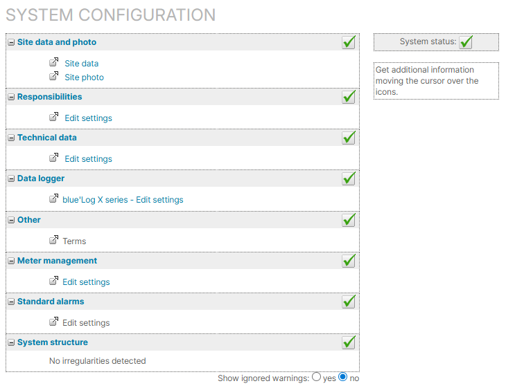
Site data and photo
Site data
If you just set up the new system, you already entered its site data, and you do not have to do anything else here. See also Site data.
Site photo
If a ![]()
Responsibilities
Assign responsibilities for certain system topics. See Responsibilities.
Technical data
If there is ![]()
![]()
Set up subsystems, to specify the system’s technical components, such as inverters, modules, or batteries, and to define a default system plan. See Subsystems.
Note on navigation
Only setting up subsystems via the updated Technical data page is described in this Help Center. But the link in the list does not yet redirect to this new page. Therefore, go directly to Technical data in the side menu. On this page you will find the Subsystems area.
Data logger
If ![]()
Add a data source or a data logger by following the steps under Data sources / data logger. For adding a blue’Log XM/XC, go directly to blue'Log XM/XC data logger.
Once you have added the data logger, close the configuration window and reopen it. The data logger and all connected devices now appear under ![]()
![]()
Also check the other configuration options under ![]()
![]()
-
To ensure alarms work properly, assign the correct scale factor to strings:
-
If your system has string inverters under String inverter inputs. You can also activate or deactivate single inputs there.
-
If you system has string combiner boxes under String combiner boxes >

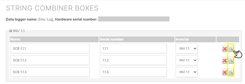
Assign scale factor to strings of string combiner boxes
-
-
Configure Other devices. See also Other devices.
-
You can configure error states (0 or 1), e.g. fault messages, under Digital signals. If you have not manually set the error state, it will be displayed as 0.
Other
Terms
With terms, you define formulas to calculate your system’s basic or user-defined data points. The term E_Z_EVU (Actual generated energy, formerly: PV yield counter) is mandatory for your system setup. Without it, basic calculation can not be performed and most of the charts can not be displayed.
To configure terms, see Terms.
Report
legacy only If displayed, the report item redirects you only to the legacy reporting module.
To directly configure new reports, see Reporting.
Meter management
When setting up the basic framework for your system, a meter of the type Solar energy meter is automatically added to your system, and you can edit its settings. See Meter.
If ![]()
Standard alarms
Before setting up your alarms, ensure no issues appear under System structure. Then set up your alarms and alarm notifications as described under Smart alarms.
System structure
If there are any issues with your configuration, they will be displayed in this section.
Examples of system structure issues
-
You need to check the assignment of inverters to subsystems.
-
You need to check that the proper scale factor is set for inverters.
If there are no system configuration issues anymore, 
FAQs
Further actions
-
Set up the power flow chart. See Power control tab
-
Set up self-consumption. See Self-consumption terms and Power flows chart.