Set up a new system
Last modified:
This topic is intended for partner admins responsible for setting up a new system (= plant) in VCOM.
Caution
If your site has multiple power plant controllers (blue’Log XC data loggers or third-party PPCs), each controller should be configured as a separate system, not as a subsystem. Otherwise, the performance ratio will not be calculated.
Example: A site has PV production across three rooftops, each with its own PPC. In this case, configure each rooftop in VCOM as a separate system.
To view the overall PR for the entire site, you can combine these individual systems into a virtual system in VCOM.
If you require further assistance, contact Support.
Prerequisites for the whole process
VCOM account and admin permissions. See User groups.
In-depth knowledge about the specific components of your system
Recommendation
Take notice of our Naming guideline when giving titles to your system components.
Prepare data
Before setting up a new system, we recommend collecting all the required information from designs, diagrams, manufacturer data sheets, and other relevant sources specific to your site and its components.
Create a new system
Steps
Once you have collected the required data, proceed as follows:
On PORTFOLIO LEVEL navigate to
.png?inst-v=4f77fa81-480e-40da-8462-282ba70567f8) Administration >
Administration >  Portfolio > New system or simply select
  New system in your System list.
Enter the general installation and site information for your system, like name, address, time zone etc. The built-in address feature helps you to automatically determine longitude, latitude, and altitude.
Select a System type:
Photovoltaic system: For this type, automatic data import with a data logger is supported. Monitoring is carried out with the portal. This is the default option.
Virtual system: Configure a new system on the basis of other systems, e.g. combine several systems into one or divide a system into several virtual systems. Also see Virtual system.
System without measurement system: For this type, no automatic data import is supported. Select this option if your system does not import data from a data logger or equivalent source (PLC, API, etc.). Nevertheless, you can record meter data manually.
Set the CO2 emission factor: The default emission factor depends on the country where the system is located. See also Savings CO2 equivalent portlet.
Add Additional information if desired, for example a mailing address.
Once all required fields are filled in, select Continue. You will be redirected to SYSTEM LEVEL >
 System configuration >
  System > System configuration for the system you just created.

System configuration overview
Complete the configurations for each step in the overview. As a rule, we recommend following the steps from the top (Installation and site) to the bottom (System structure). However, this may not always be possible. You can exit the system configuration and return to it at any time.
Note
A green check mark  indicates that all fields have been completed for a step. To ignore the step and set the check mark anyway, select Ignore.
Installation and site
Note
Also find the general information on Installation and site in the area System data of the separate sidebar item Technical data (SYSTEM LEVEL > ![]() System configuration >
System configuration > ![]() System).
System).
Site data: Edit the general information on installation, that you already entered when you initially created the new system.
Plant photos: Add a photo of your site.
Responsibilities
Note
Also find the information on Responsibilities as a separate item in the sidebar (SYSTEM LEVEL > ![]() System configuration >
System configuration > ![]() System).
System).
Assign contacts for the various responsibilities:
If you have already set up users and contacts: Assign existing users or contacts to responsibilities via the arrow button.
If you have not set up users and contacts: Set up new users and contacts via Set up new contact or Create new user.
For more information on users and contacts, see Users and contacts.

Assign users or contacts to responsibilities
Technical data
Note
The user interface of this section was completely updated in May 2025. To learn more about these changes, see Update 2025: Technical data and subsystems wizard.
Note
Also find the information on Technical data as a separate item in the sidebar (SYSTEM LEVEL > ![]() System configuration >
System configuration > ![]() System).
System).
Technical data is divided into two areas: System data and Subsystems.
System data
The general installation and site information of your system are displayed in the System data area. Select ![]() Edit to change these information.
Edit to change these information.

Overview of the system data
Subsystems
Add PV and battery subsystems to your main system.
A PV SUBSYSTEM is a group of PV modules configured with distinct characteristics such as different orientations, physical locations, or electrical configurations. Each subsystem operates independently but can be grouped within a single system in VCOM.
With a BATTERY SUBSYSTEM you specify the battery inverters’ inputs and the installed capacity of your battery.
Caution
If your site has multiple power plant controllers (blue’Log XC data loggers or third-party PPCs), each controller should be configured as a separate system, not as a subsystem. Otherwise, the performance ratio will not be calculated.
Example: A site has PV production across three rooftops, each with its own PPC. In this case, configure each rooftop in VCOM as a separate system.
To view the overall PR for the entire site, you can combine these individual systems into a virtual system in VCOM.
If you require further assistance, contact Support.
Prerequisites
BATTERY SUBSYSTEM To add a battery subsystem, you must purchase a license for the VCOM module Battery monitoring and activate the module for the specific system. See VCOM Battery monitoring module.
Steps
Select
New subsystem to add a new PV or battery subsystem.A window with a step-by-step wizard appears.
Follow the steps of the wizard.
A wizard will guide you through the process of adding a subsystem
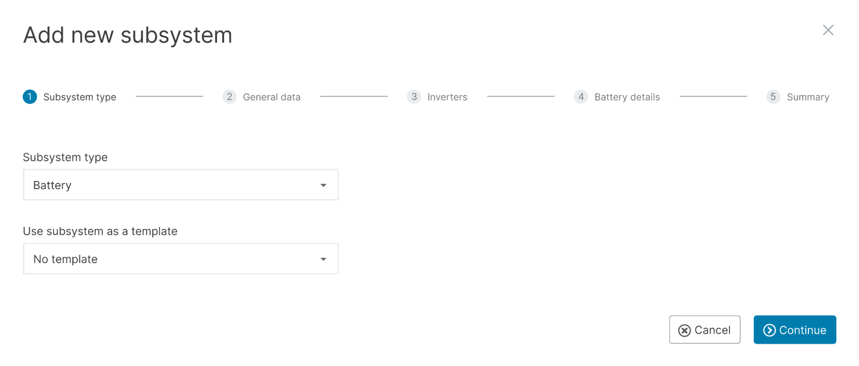
1) Subsystem type
Select a Subsystem type from the dropdown, choose between:
PV
Battery
Use a subsystem as a template: If, at a later stage, your system already has a subsystem of the type you have chosen, you will be able to select a previously added subsystem as a template. The data fields described below (except for title) will be prefilled and can be edited as needed.
2) General data
Enter a Title for your subsystem.
Recommendation
Take notice of our Naming guideline when giving names and titles.
Enter the Date of installation of your subsystem.
PV SUBSYSTEM: If you use a tracking system (solar tracker), select the type under Trackers.
3) Inverters
Note
Each subsystem can only have one type of inverter, but it can have multiple inverters of the same type.
Select the Inverter manufacturer. If you can not find the desired manufacturer, send a request to technics@meteocontrol.com including the manufacturer’s website or data sheet. We will get back to you with any further questions or let you know if we added it to the list.
When a manufacturer is selected, you can select the Inverter type. If you can not find your inverter type in the list, select
New inverter type and fill in the inverter details in the popup window. If required, refer to the manufacturer's data sheet for details.Enter the Number of inverters in your subsystem.
4) Inputs
Note
The configurations for your inverter inputs apply to all inverters of your subsystem. If some of your inverters differ in terms of the number of strings per input and the modules per string, adjust the nominal power of the subsystem manually in step 5) Summary.
The input fields for the inverter inputs differ depending on your previous selections on subsystem type, inverter type, and number of inputs.
Steps for a PV SUBSYSTEM
All inverter inputs (MPPTs) are listed in the sidebar of the wizard. Go through each MPPT and enter the details:
Select if the MPPT is Allocated or Not allocated.
Under Installation details, enter the Tilt (inclination) and Orientation of the modules, as well as the Type of installation. The orientation is the deviation from the north (clockwise). For example, orientation 0° means north, and 180° means south.
Under PV modules and circuitry, enter the Number of strings, Modules per string, Module manufacturer, and Module type. If your module type is not in the list, select
New module type and enter the module details in the appearing window. Refer to the manufacturer’s data sheet for the relevant information.Select the next MPPT from the sidebar. You can now use the data from MPPT 1 as a template for MPPT 2, MPPT 3, etc., and edit the details as needed. For this, select
 Copy data from MPPT and select the MPPT from which you want to copy the data. The data fields will be prefilled and can be edited as needed.
Steps for a BATTERY SUBSYSTEM
All inputs (busbars) are listed in the sidebar of the wizard. Go through each busbar and enter the specifications:
Select if the busbar is Allocated or Not allocated.
Under Capacity, enter the rated capacity at the beginning of the life of your battery.
Proceed as described with all the other busbars in the sidebar.
5) Summary
View a Summary of the subsystem and make final adjustments.
Summary for a PV SUBSYSTEM
The summary shows the Total module area and the nominal Power of the PV subsystem, which is calculated based on nominal voltage and current. Edit the module area and nominal power manually, for example, when the subsystem has strings with differing numbers of modules.
 Save your PV subsystem, and it appears as separate section in the area Subsystems, where you can
  Edit and
  Delete it later.
Summary for a BATTERY SUBSYSTEM
The summary shows the Total capacity of your battery subsystem, which is is calculated as follows: (Sum of capacity of all allocated busbars) * (Number of inverters). Sometimes the calculated number deviates from the predefined rated capacity of the battery.
- Save your battery subsystem, and it appears as separate section in the area Subsystems, where you can Edit and Delete it later.

PV and battery subsystems are displayed separately in the area Subsystems
Data logger
In addition to the blue’Log XM/XC from meteocontrol, you can add data loggers from many different manufacturers. Alternatively, you can import data via manufacturer APIs or predefined imports.
For a blue’Log, follow the steps under Data sources / data logger. In addition, we recommend activating the Support access toggle on your blue’Log if you have not already done so. See https://help-center.meteocontrol.com/blue-log-xm-xc/?contextKey=user&version=latest&language=en .
Once you have added the data logger, close the configuration window and reopen it. The data logger and all connected devices should appear under
System configuration >  Data sources > Data logger overview.
Note
The items displayed under Data logger overview will vary depending on your data source.
Inverter
See Inverters
Current sensors
To ensure the alarms work properly, assign the correct scale factor in kW to each subsystem via the
 Magnifying glass.
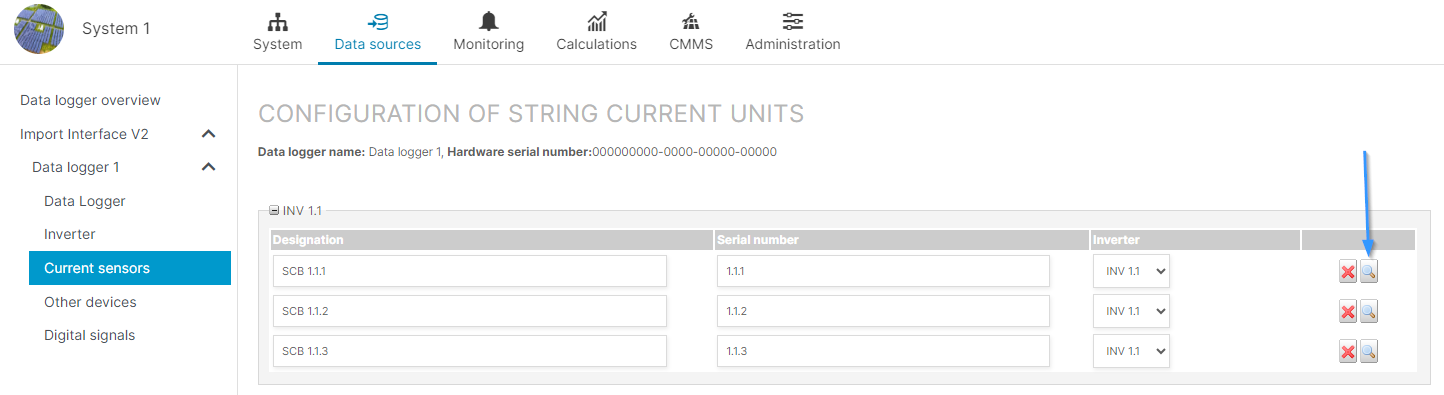
Assign scale factor to string combiner box sensors
Other devices
See Other devices
Digital signals/inputs
You can configure error states (0 or 1), e.g. fault messages, under Digital signals. If you have not manually set the error state, it will be displayed as 0.
String inverters and stringboxes
It is also possible to configure string inverters and stringboxes (string combiner boxes) if these are included in your imported data.
Other (terms)
Any additional settings required by your system will appear here, for example Terms.
Warning
The terms E_Z_EVU and G_M0 are required for your system setup. Without them, many calculations and charts will not be displayed. See Terms to check and configure them.
Meter
For a blue’Log: Once you have finished setting up your blue’Log in VCOM, the data from your yield meter is automatically imported. We recommend double-checking the following under System >
System configuration > Meter management > Edit meter:Measured value assigned: In general, you should select the term E_Z_EVU.
Installation date: when the data logger was commissioned
For a different data logger: The data may not be automatically imported if your data logger does not deliver data (check the manufacturer data sheet for information). In this case, you can manually add a meter.
Monitoring
Before setting up your alarms, ensure no issues appear under System structure. Then set up your alarms and alarm notifications as described under Smart alarms.
System structure
If there are any issues with your configuration, they will be displayed here.
Examples of system configuration issues
You need to check the assignment of inverters to subsystems
You need to check that the proper scale factor is set for inverters
If there are no system configuration issues anymore green check marks  should appear next to all items under System configuration.
Next steps
Set up the power flow chart. See Power control tab
Set up self-consumption. See Self-consumption term and Self-consumption chart
FAQs
You can edit the transmission rate in VCOM under ![]() System configuration >
System configuration > ![]() Data sources > Data logger overview. To edit, select the pencil icon next to Measuring interval.
Data sources > Data logger overview. To edit, select the pencil icon next to Measuring interval.
Alternatively, you can set the data transmission rate on your data logger. For this, see the blue’Log documentation.