Last modified:
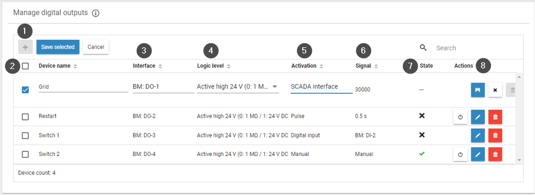
Digital outputs allow you to control activities that can have two states, e.g. turn something off or on. You can activate digital outputs from the bluelog and Multi I/O MX add-on modules. A digital output stays active if you reboot the software and if the activation signal is still active. Only a hardware reset or disruption of the power supply to the bluelog will deactivate the digital output.
|
Item |
Name |
Details |
|---|---|---|
|
1 |
Plus |
Add a new digital output |
|
2 |
Device name |
Enter a device name |
|
3 |
Interface |
Select the digital output |
|
4 |
Logic level |
Select the logic level |
|
5 |
Activation |
Select how the digital output is activated |
|
6 |
Signal |
For a pulse or digital input, specify the activation state
|
|
7 |
State |
Shows whether the digital output is currently activated/deactivated |
|
8 |
Actions |
|
Add a digital output
Prerequisites
-
Your bluelog is connected to the network.
-
The basic configuration of your bluelog has been completed.
-
All bluelog updates have been performed. See Update.
-
Add-on modules, if required, are connected. See Add-on modules.
Steps
-
Navigate to Devices > Digital output > Manage digital outputs.
-
Select the Plus to add a new digital output.
-
Enter a name for the digital output.
-
Select the interface and logic level (settings depend on the connection type).
-
For explanations of the abbreviations, see Digital inputs, digital outputs, and multi-inputs.
-
-
Choose the signal that activates the digital output.
-
If selecting a SCADA interface, the register is assigned automatically.
-
If selecting a pulse or digital input, define the activation settings under Signal. See Activation signals for digital outputs.
-
-
Select the Save icon to save the settings.
-
Confirm that the digital out put is active by checking the State column:
-
Check mark: activated
-
X mark: not activated
-
|
Interface abbreviation |
Meaning |
|---|---|
|
BM |
Base module |
|
MX |
MX module |
|
DI |
Digital input |
|
MI |
Multi input |
|
DO |
Digital output |
|
e.g. MX-1: RS485-2 means the RS485-2 interface of the first connected MX module |
|
Interface abbreviations and meanings
Activation signals for digital outputs
Digital outputs can be activated and deactivated in the following ways:
|
Method |
Description |
|---|---|
|
Manually |
A Power button icon appears on the right side of the configuration, allowing you to manually switch the digital output. |
|
SCADA interface |
The output can be switched via a SCADA address (SCADA interface License required). Every digital output is automatically assigned to a Modbus register by the system. For more information, see the SCADA Interface bluelog Neo license data sheet. SCADA signal requirements
|
|
Digital input |
|
|
Pulse |
Digital outputs can be switched with pulses from 0.5 to 5 seconds (user-defined) |