Last modified:
Caution
Installation, commissioning, and maintenance must be carried out by a qualified electrician. They must follow all applicable safety laws, installation regulations, good practice standards, and all instructions in this manual.
Damaged devices must be removed from operation immediately.
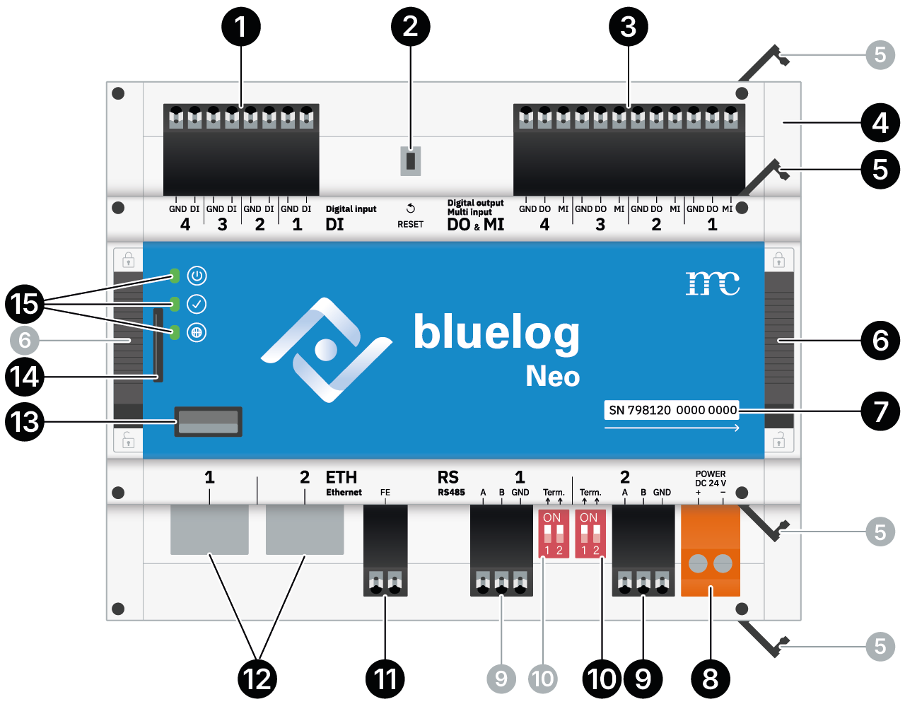
Device overview
|
1 |
4x Digital input (DI-1 … DI-4) |
|
2 |
Reset button |
|
3 |
4x Digital output (DO-1 … DO-4) / Multi input (MI-1 … MI-4) |
|
4 |
Side caps. To expand with add-on modules, remove right-hand one. |
|
5 |
4x Fasteners on each side to remove side caps. |
|
6 |
DIN top-hat rail latches on each side |
|
7 |
Device serial number |
|
8 |
Power supply: 24 V |
|
9 |
2x RS485 interface (RS485-1 + RS485-2) |
|
10 |
2x Corresponding bus termination for each (9) |
|
11 |
FE terminal. Do not connect. |
|
12 |
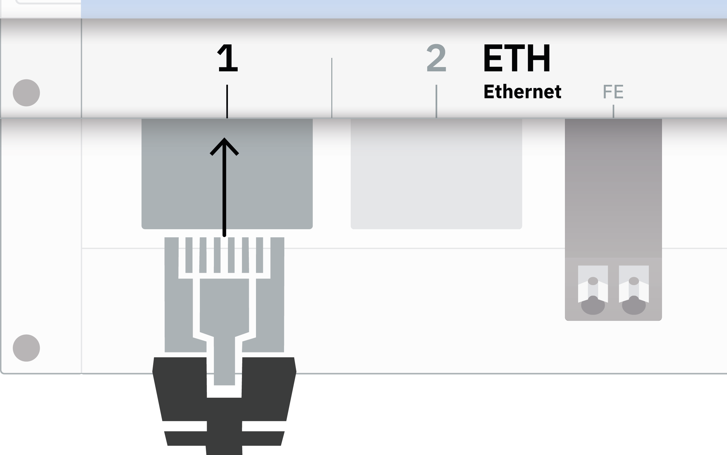
2x Ethernet port (ETH-1 + ETH-2) |
|
13 |
USB port |
|
14 |
Memory card slot |
|
15 |
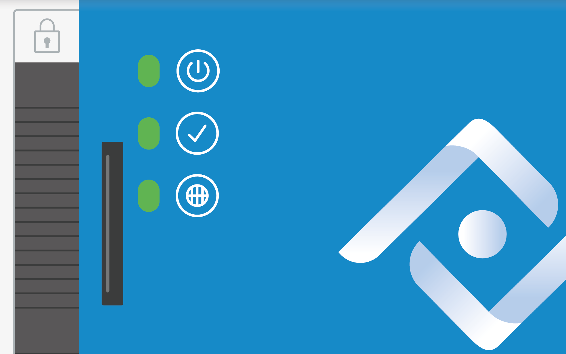
LEDs: |
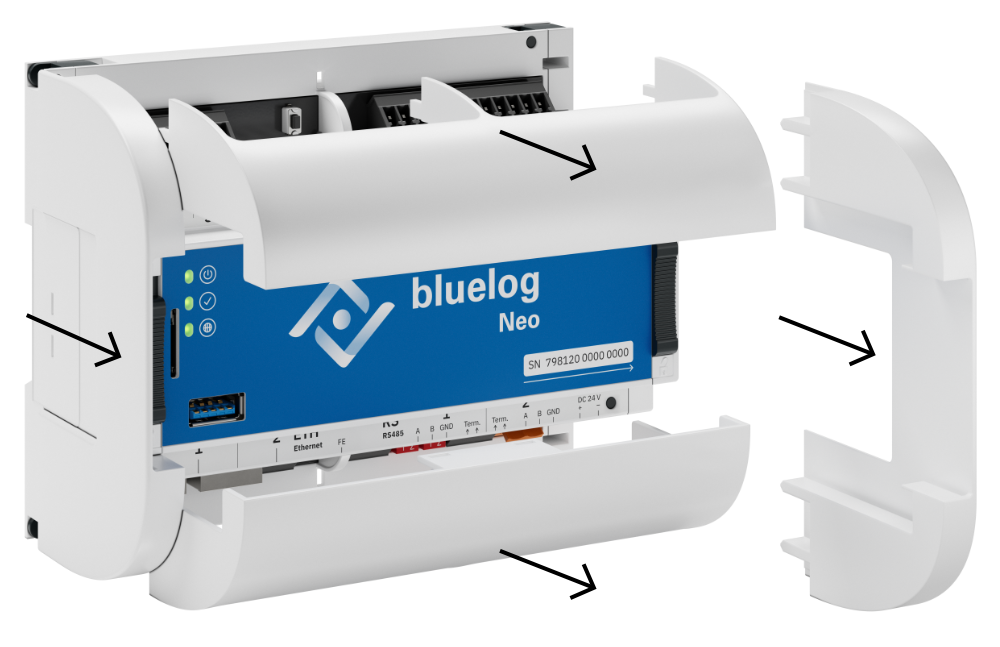
Remove protective covers
Pull the upper, lower, left, and right protective cover forward to see the port labeling.
Caution
Opening the bluelog beyond the protective covers, or any other modification or alteration, will void operating license and warranty claims.
1 Mount the bluelog
Caution
Only install the bluelog indoors, or outdoors in a standardized protective enclosure.
Notice on add-on modules
If applicable, connect all add-on modules to the base module before mounting the whole unit. See Mount add-on modules.
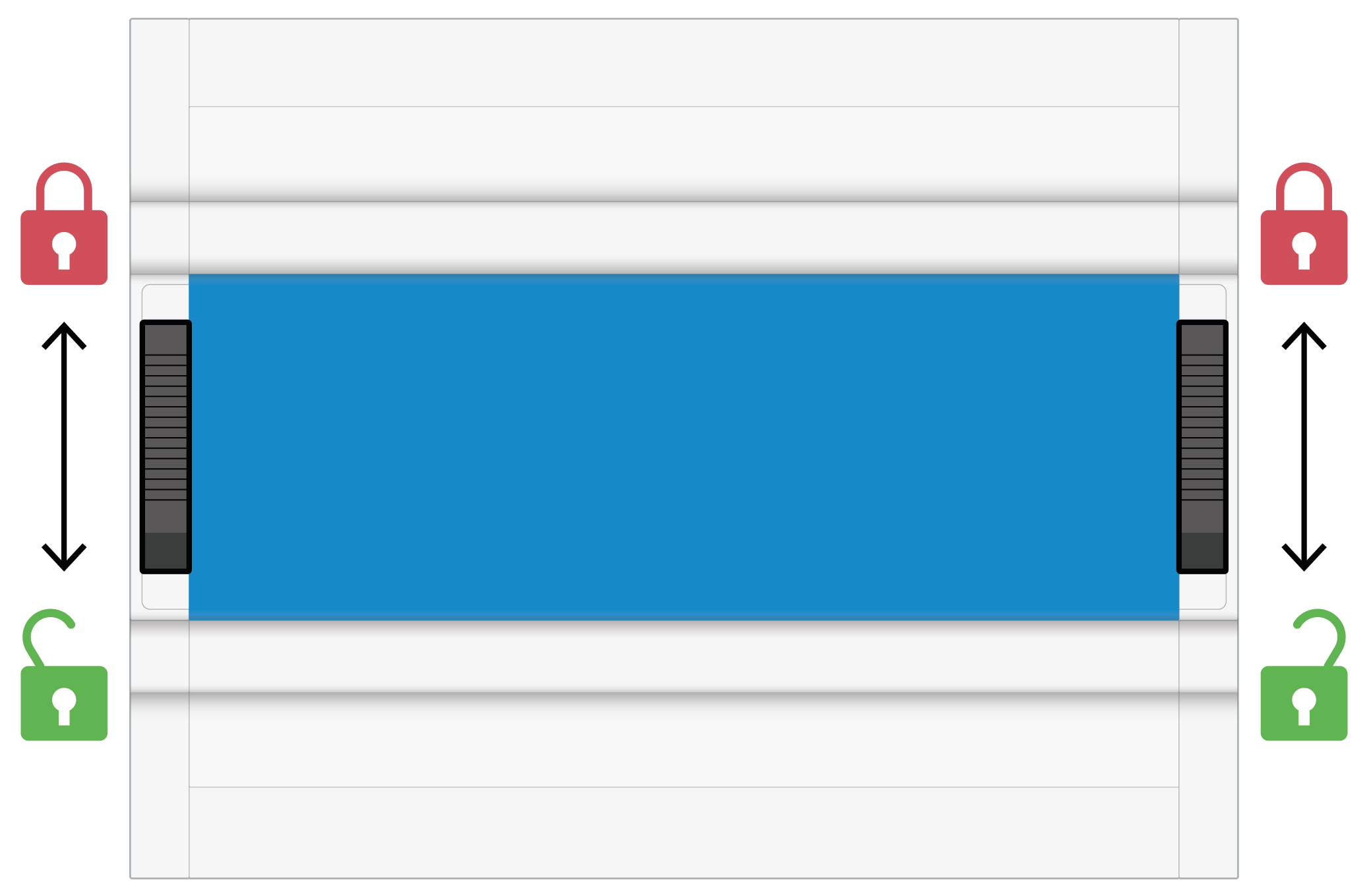
A) On a top-hat rail
-
Slide the left and right DIN top-hat rail latches downwards to

-
From above, hook the bluelog onto the DIN rail and press down.
-
Slide both latches upwards to

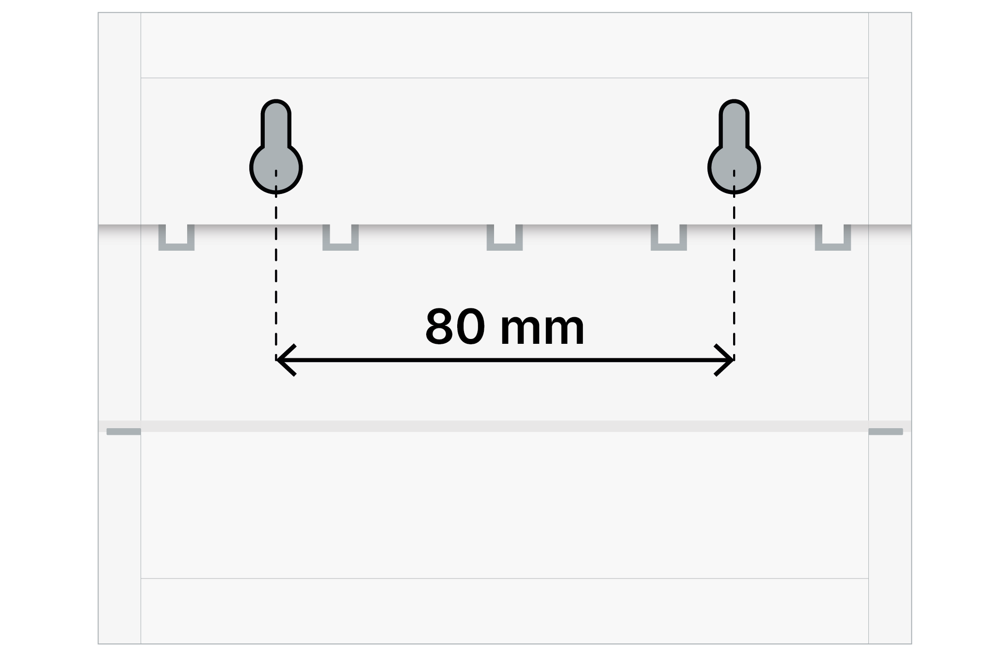
B) On a wall
-
Fasten two screws into the wall at a distance of 80 mm apart.
-
Place the bluelog on the screws using the inlets on the rear side.
-
Push the bluelog down. Check that it is correctly mounted.
2 Connect the network and devices
2.1 Connect bluelog to your network
-
Connect one end of the enclosed Ethernet patch cable to a LAN network, for example, router, LAN interface PC, or switch.
-
Connect the other end of the cable to the ETH-1 port.
2.2 Connect devices
Caution
Applying impermissible signals and signal strengths to the bluelog and its add-on modules may cause damage to them.
-
Check if your devices are compatible. See bluelog compatibility check.
-
Connect your devices according to the respective plan. See Device connection plans.
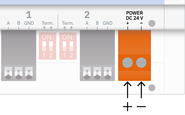
3 Supply power
Caution
Failure to observe the correct polarity (+/-) may cause damage to the bluelog. Use an energy-limited circuit or a DC power source with limited power. The power supply must comply with the following specifications:
-
Voltage: 24 V DC (+/- 10%)
-
Power: max. 80 W
-
Connect the power supply with the Power port.
-
The LEDs light up as follows:
-


-


-

-
-
Wait for the
If the ![]()
![]()
4 Configure the bluelog in your network
A) With DHCP server
The IP address is assigned by the DHCP server.
Find the current IP address either in your personal network administration or in the web interface of the bluelog Neo in the next step.
B) Without DHCP server
The IP address is generated randomly by the bluelog.
Range: 169.254.XXX.XXX
5 Configure settings
5.1 Open web interface
Enter the bluelog’s host name in the address bar of your internet browser. Or, if you already know the IP address, you can enter that.
Structure of bluelog’s host name:
-
DNS, Netbios:
https://blue-nnnnnnnn -
No DNS, Netbios:
https://blue-nnnnnnnn.local
n = last 8 digits of bluelog’s SN/serial number from the front panel
5.2 Register user
When accessing the web interface for the first time, you must register the first user.
-
In the window that appears, assign a new Username and Password. You will use these credentials for all subsequent sign-ins.
-
Enter an Email address. This is necessary for any password resets.
-
Select Confirm to complete the user registration.
You arrive at the bluelog web interface. The setup wizard opens automatically.
Recommendation
Activate the toggle Support access to allow our support team to remotely access your device in case of troubleshooting.
5.3 Carry out essential settings
Select Start wizard, which will guide you through further essential configuration of your connected devices, including:
-
Install any available updates.
-
Choose the correct timezone.
-
If required, configure the Ethernet.
-
Add your connected devices (inverters, meters, etc.).
5.4 Connect to VCOM
Prerequisites
-
You have set up a system in VCOM.
-
On the bluelog Neo, the LED


A) Via bluelog setup wizard
-
In the setup wizard, select PV-Plant > VCOM.
-
Enter the VCOM System name, System key, and your VCOM Username and Password.
-
Select Register.
-
Under Automatic transmission, set the Transmission interval, which determines how often all the logged data is sent to VCOM.
B) Via VCOM
-
In VCOM at the system level, select System settings > Data sources > Data logger overview.
-
Under New source of the type, select bluelog Neo. Select Add.
-
Enter the SN/Serial number of the bluelog (find this directly on the device or in the footer of the web interface).
-
Enter the sign-in credentials you assigned in step 5.2.
-
Select Add to add the bluelog to the VCOM system.
-
Set the aggregation Interval that VCOM uses to aggregate data for charts, under Measured value aggregation.