
Last modified:
Note: Beta feature
Telecontrol is currently available as a beta feature
About the formula editor
The Formula editor is a graphical interface that allows you to create visual graphs. Using the nodes in the editor, you can create a formula (calculation rule) and select the values you want to use in the formula. Examples of common formulas:
-
Forward setpoints (command telegrams) to the bluelog PPC.
-
Submit values (information telegrams) from the plant to the grid operator (general interrogation/group interrogation/cyclic or reactive transmission).
-
Limit remote switch events to the site, e.g. do not switch if a person is on-site.
-
Calculate values that are not available by default in the bluelog, but which are required by the grid operator.
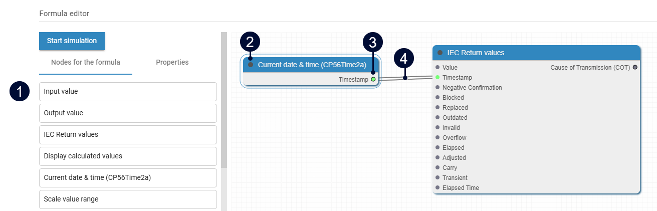
|
Item |
Description |
|
|---|---|---|
|
1 |
Nodes for the formula |
List of available nodes. |
|
2 |
Input slot |
Connection point on a node that receives data from another node's output. An input slot can only have one connection at a time. |
|
3 |
Output slot |
Connection point that sends data to the inputs of one or more nodes. An output slot can have multiple connections at a time. |
|
4 |
Connection |
Connection between two nodes. |
About nodes
-
Nodes are the building blocks for formulas. The links between nodes represent data flow. The visual graph represents the formula.
-
Depending on its individual properties, each node can have slots that allow you to connect the nodes and add operations.
-
Drag a node into the right-side area using drag & drop.
-
You can only link input slots (left side of the node) to output slots (right side of the node).
-
You can link nodes if the data type allows it. For example, a boolean can not be connected to a date or time data type.
-
Where relevant, double-click on the node to edit its properties. Alternatively, select the node and edit the properties via the Properties tab in the side bar.
-
To remove a node, select it, then select Remove. Alternatively, select the node and hit “delete” on your keyboard.
Node types
The formula editor has the following types of nodes:
Telecontrol-specific nodes
|
Node |
Description |
Properties |
Input slots and selection |
Output slots |
|---|---|---|---|---|
|
Input value |
Value of a configured value point in the formula |
|
Selection:
|
|
|
Output value |
Submit a (calculated) value to an output value point |
|
Slot:
Selection:
|
|
|
IEC return value |
Submit (calculated) values to the grid operator. |
|
Slots:
Quality bits (COT):
|
|
|
IEC command |
Receive a command from the grid operator to perform an action on-site. Examples:
|
|
|
|
|
IEC command output
|
Return quality bit information via IEC for command telegrams |
|
Slots:
|
|
|
Display calculated values |
Watch and display multiple (calculated) values at once to test the formula. Simulation mode only. |
|
Slot:
|
|
|
Scale value range |
Scales an input value from a defined source range to a corresponding value in a target range, e.g. to calculate an alternative output or a percentage. |
|
Slot:
|
|
Basic nodes
|
Node |
Description |
Properties |
Input slots and Selection |
Output slots |
|---|---|---|---|---|
|
Time |
Current time for time-dependent functionality of the formula. |
|
|
|
|
Constant number |
Constant numeric value. |
|
Selection:
|
|
|
Constant boolean |
Constant boolean value. |
|
Selection:
|
|
|
Constant string |
Constant string value. |
|
Selection:
|
|
|
Length of value |
Returns the length of strings. |
|
Slot:
|
|
Math nodes
|
Node |
Description |
Properties |
Input slots / Selection |
Output slots |
|---|---|---|---|---|
|
Convert to number |
Converts any input value to a numeric type |
|
Slot:
|
|
|
Random value |
Generates random numbers within a specified range. |
|
|
|
|
Clamp value |
Restricts a value to be within a specified range. |
|
Slot:
|
|
|
Absolute value |
Calculates the absolute value of the input. |
|
Slot:
|
|
|
Round down |
Rounds down to the nearest integer. |
|
Slot:
|
|
|
Fractional part |
Returns the fractional part of a number. |
|
Slot:
|
|
|
Pass value |
Selects between two inputs based on a boolean condition. When the control signal is true, the node passes input A through. When false, it passes input B. Can be used e.g. for choosing between different data sources or control paths. |
|
Slots:
|
|
|
Math operation |
Process two inputs using one of the following mathematical operations: When using this node, the OP (operation) must be defined. |
|
Slot:
|
|
|
Compare values |
Compares two values and returns boolean results for different comparison operators. |
|
Slots:
|
|
|
Evaluate condition |
Evaluates one of the following conditions between two values and returns true/false results: The output value of each slot is a boolean (true/false). The output value needs to be converted to a number when used in output value points. |
|
Slots:
Selection:
|
|
|
Branch by condition |
Sends the input value to one of two outputs based on a condition. Output:
|
|
Slots:
|
|
String nodes
|
Node |
Description |
Properties |
Input slots |
Output slots |
|---|---|---|---|---|
|
Convert to text |
Converts any numbers or booleans to a string |
|
|
|
|
Compare text |
Compares two strings and returns boolean results for different comparison operators. |
|
|
|
|
Join text |
Joins two strings to form a single string |
|
|
|
|
Text contains |
Checks whether a string contains a character. The output is a boolean (true/false) |
|
|
|
|
Uppercase text |
Converts a string from lowercase to uppercase text. |
|
|
|
|
Split text |
Splits strings using a comma ( The output is an array of values |
|
|
|
Logic nodes
|
Node |
Description |
Properties |
Input slots |
Output slots |
|---|---|---|---|---|
|
AND |
Logical operator that returns true if all inputs are true. |
|
|
|
|
OR |
Logical operator that returns true if at least one input is true. |
|
|
|
|
NOT |
Logical operator that returns the logical negation of the input. |
|
|
|
|
Compare booleans |
Compares whether boolean values are equal. |
|
|
|
Example formulas
Calculate values that are not on the bluelog: Scale a data point
-
Example: Convert kW to MW
-
Formula:
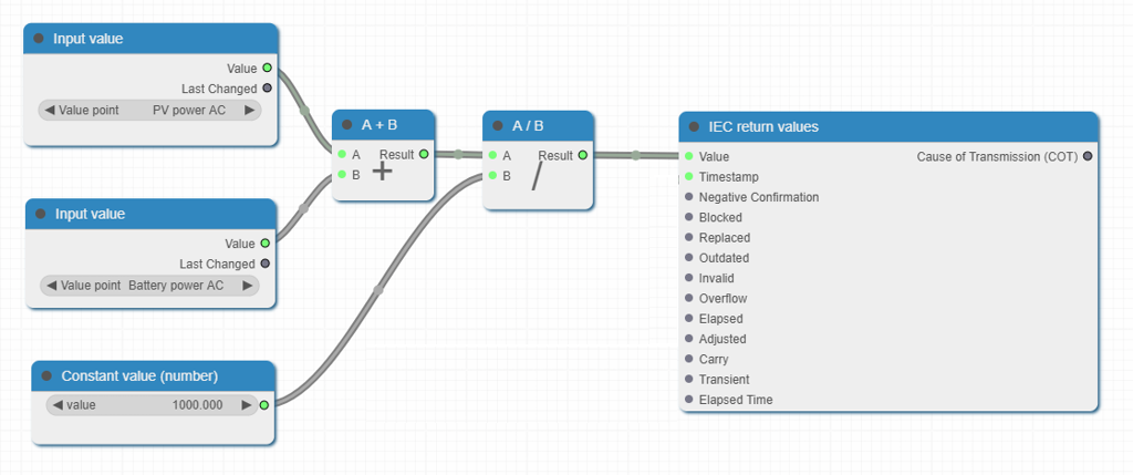
AC power PV + AC power Battery / 1000 = Result
Steps
-
Use a suitable TI (15/16/37, etc.).
-
Define the input value points
PV power ACandBattery power AC, selecting the corresponding Device type, Device ID, and Reference value. -
Define the formula by adding nodes:
-
Input value node: select the data point
PV power AC. -
Input value node: select the data point
Battery power AC. -
Constant value (number) node: Define the constant
1000. -
Add the input value points together using the mathematical operation
+. -
Math operation node: Divide the sum of the data points by the constant using the mathematical operation
/. -
IEC return values node
-
Information telegram: Confirm active power setpoint
Steps
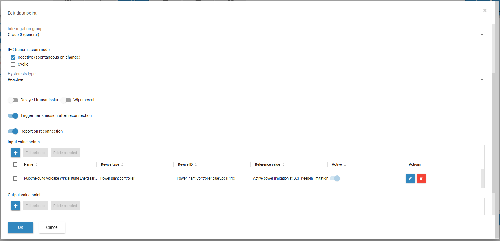
-
Create a data point with the IOA / TI / ASDU address.
-
Define the transmission mode (reactive without hysteresis recommended for e.g. feedback active power)
-
For the input value point, select the PPC value for Active power feed-in limitation (grid operator, relative) (
PPC_GCP_P_LIM_FEEDIN_REL). -
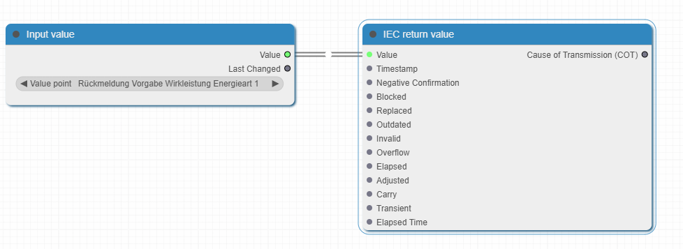
Define the formula: Assign the value point to return the value using IEC (1:1 assignment). Connect the Value slots of the following nodes:
-
IEC command node
-
Output value node
-
Command telegram: Receive grid operator setpoint and forward to PPC
Steps
-
Create data point with given IOA / TI / ASDU address.
-
For the output value point, select the PPC value for Active power feed-in limitation (grid operator, relative) (
PPC_GCP_P_LIM_FEEDIN_REL).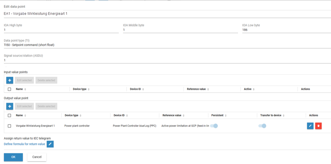
Receive grid operator setpoint and forward to PPC: Configuration -
Define the formula: Assign the IEC command value to the output value point's value (1:1 assignment). Connect the Value slots of the following nodes:
-
IEC command node
-
Output value node
-
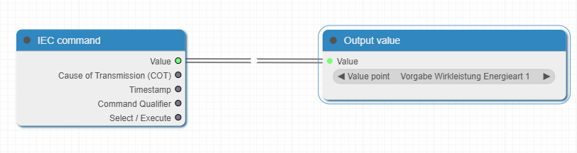
Double command telegram: Indicate that a person is on-site
Warning
This is an essential safety mechanism for many plants and recommended best practice. It indicates that personnel are working on the equipment. When the signal is active, remote switching commands are blocked for safety reasons.
Steps
-
Define output data points (switch bits).
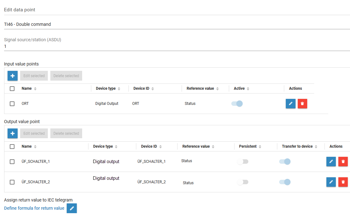
Indicate that a person is on-site: Configuration -
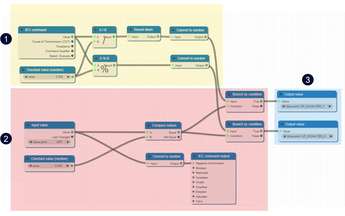
Define the formula:
|
Part of formula |
Description |
|||||||||||||||||||||
|---|---|---|---|---|---|---|---|---|---|---|---|---|---|---|---|---|---|---|---|---|---|---|
|
1 |
Calculation of the bit value |
Depends on numeric value:
|
||||||||||||||||||||
|
2 |
Security mechanism |
Use the Branch by condition node: Condition: Parameter Result: Bit values for the switch command are only transferred if IEC command output node (optional): Some grid operators require a negative confirmation if no switch is performed. |
||||||||||||||||||||
|
3 |
Output values |
Two possible output values. The output value depends on the result of the security mechanism. |
Double information telegram (feedback for switch operations)
Steps
-
Define data point with TI 31.
-
Under IEC transmission mode, select Reactive.
-
Activate the toggle

-
Select the

-
Define a suitable delay for the values 0 and 3, e.g. 2000 ms.
-
Select


-
Define input value points for both bits (0/1).
-
Define the formula.
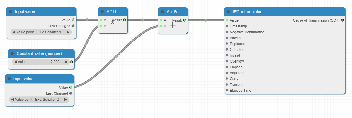
Double information telegram: Formula