Last modified:
Note
The content on this page refers only to the blue'Log XC combined with the Hybrid EMS licence.
The reactive power setpoint is the target value a plant should maintain to ensure grid stability and compliant operation. It is either communicated by the grid operator or calculated by the controller.
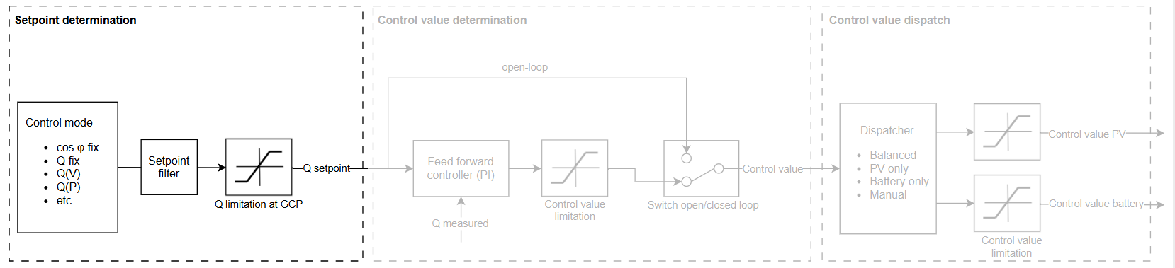
The controller determines the reactive power control setpoint based on the power control mode you select. You can use a setpoint command or a characteristic curve as a power control mode. The reactive power controller can further adapt the setpoint by applying a Setpoint filter and reactive power limitations at the grid connection point (GCP).
Setpoint command modes
The setpoint is either transmitted via an interface (analog input, digital input, Modbus) or entered manually in the user interface (fix).
Characteristic curve control modes
The controller measures grid parameters and determines a corresponding setpoint autonomously.
Configure the reactive power control mode
Prerequisites
-
If using a Modbus mode, e.g. Q(Modbus): Modbus Power Control license
-
A meter is set up.
Steps
-
Go to Power Control > Reactive power.
-
In the Control mode dropdown, select the desired control mode.
-
Under

The reactive power control mode is now configured.
Note
To switch between different control modes, you can enable the Method switch for reactive power control.
Reactive power limitation at grid connection point (GCP)
The controller can be configured with reactive power limits that shall not be exceeded at the grid connection point. This reduces overshoots during fast changes in network conditions.
Caution
The reactive power limits at the grid connection point are not guaranteed in open-loop mode, as no feedback value is considered. In open-loop, only the setpoint and thus also the control value sent to the plant are limited.
Configure reactive power limits under Power Control > Reactive Power > Power limitation at grid connection point (GCP).