blue'Log XM/XC

Part 3: Control value dispatch

Last modified:


Note

The content on this page refers only to the blue'Log XC combined with the Hybrid EMS licence.

The dispatcher distributes the reactive power control value among the plants if multiple plants are controlled at a single grid connection point. Furthermore, settings for the format of the control value and its limitations can be adjusted.
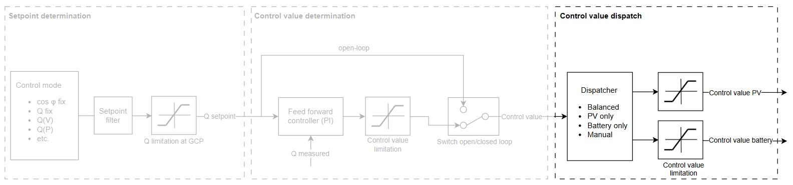
image-20260206-143902.png
Reactive power controller: control value dispatch

Dispatch modes

The following dispatch modes are available:

Balanced

The required reactive power is provided equally by the PV and battery plant, depending on their maximum apparent power.

📗

Example

Smax,PV = 10 MVA    Smax,battery = 5 MVA

  • Share of reactive power provided by the PV plant: QPV  = Smax,sum / Smax,PV = 2/3

  • Share of reactive power provided by the battery plant: QBattery = Smax,sum / Smax,battery = 1/3

The PV system provides 2/3 of the required reactive power and the battery system 1/3. If the required reactive power is, e.g. 6 MVAr, the following control values are sent to the plants:

  • Qcontrol value, PV = 2/3 * 6 MVAr = 4 MVAr (40% Smax,PV)

  • Qcontrol value, battery = 1/3 * 6 MVAr = 2 MVAr (40% Smax,battery)

Consequently, both plants receive the same relative control value.

PV only

Only the PV plant provides reactive power.

Battery only

Only the battery plant provides reactive power.

Manual

The share of reactive power supplied by the battery can be individually configured. The remaining demand is covered by the PV system.

📗

Example

Dispatch share of the battery = 50%

The battery provides 50% of the reactive power, and the PV system provides the remaining 50%. If the required reactive power is, e.g. 6 MVAr, this translates in the following control values sent to the plants:

Qcontrol value, PV = 50% * 6 MVAr = 3 MVAr (30% Smax,PV)

Qcontrol value, battery = 50% * 6 MVAr = 3 MVAr (60% Smax,battery)

Configure the dispatch mode

Prerequisites

  • Both a PV and a battery plant are configured under Plant data (Hybrid EMS). Otherwise, the feature is not available.

Steps

  1. Navigate to Power Control > Reactive Power > Controller settings.

  2. Select the desired mode under Dispatch mode.

    • If you selected Manual, enter the percentage of reactive power to be supplied by the battery.

Dispatch is configured.

Control values and limitations

The control values calculated by the dispatcher are sent to the PV and battery inverters.

  • The control values can be sent to the inverters either as Q values (-100% to 100%) or as cos φ values (-1 to 1). The format required depends on the inverters. Usually, Q values are sent.

    • To determine the format, search for your inverter in the Compatibility Check. Under Power control, check whether Q and/or cos φ control are possible.

  • Furthermore, the control values can be limited by an upper and lower limit

  • To configure the format (Q or cos φ) and limitation, go to Power Control > Reactive power > Extended settings > Control value.