Last modified:
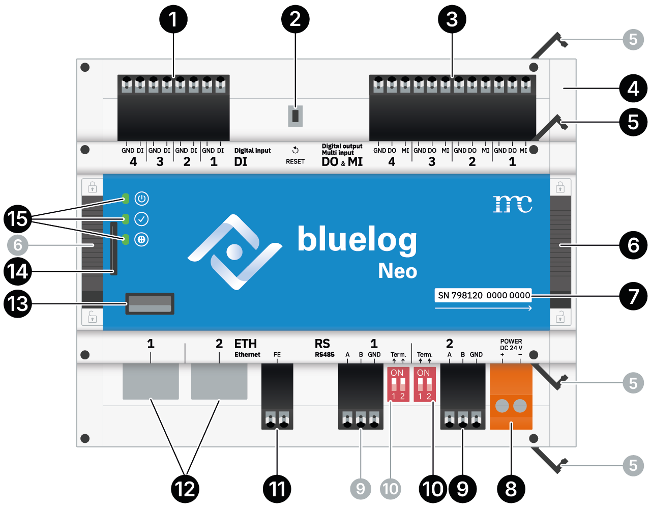
Front panel
|
1 |
4x Digital input (DI-1 … DI-4) |
|
2 |
Reset button |
|
3 |
4x Digital output (DO-1 … DO-4) / Multi input (MI-1 … MI-4) |
|
4 |
Side caps. To expand with add-on modules, remove right-hand one. |
|
5 |
4x Fasteners on each side to remove side caps. |
|
6 |
DIN top-hat rail latches on each side |
|
7 |
Device serial number |
|
8 |
Power supply: 24 V |
|
9 |
2x RS485 interface (RS485-1 + RS485-2) |
|
10 |
2x Corresponding bus termination for each (9) |
|
11 |
FE terminal. Do not connect. |
|
12 |
2x Ethernet port (ETH-1 + ETH-2) |
|
13 |
USB port |
|
14 |
Memory card slot |
|
15 |
LEDs: |
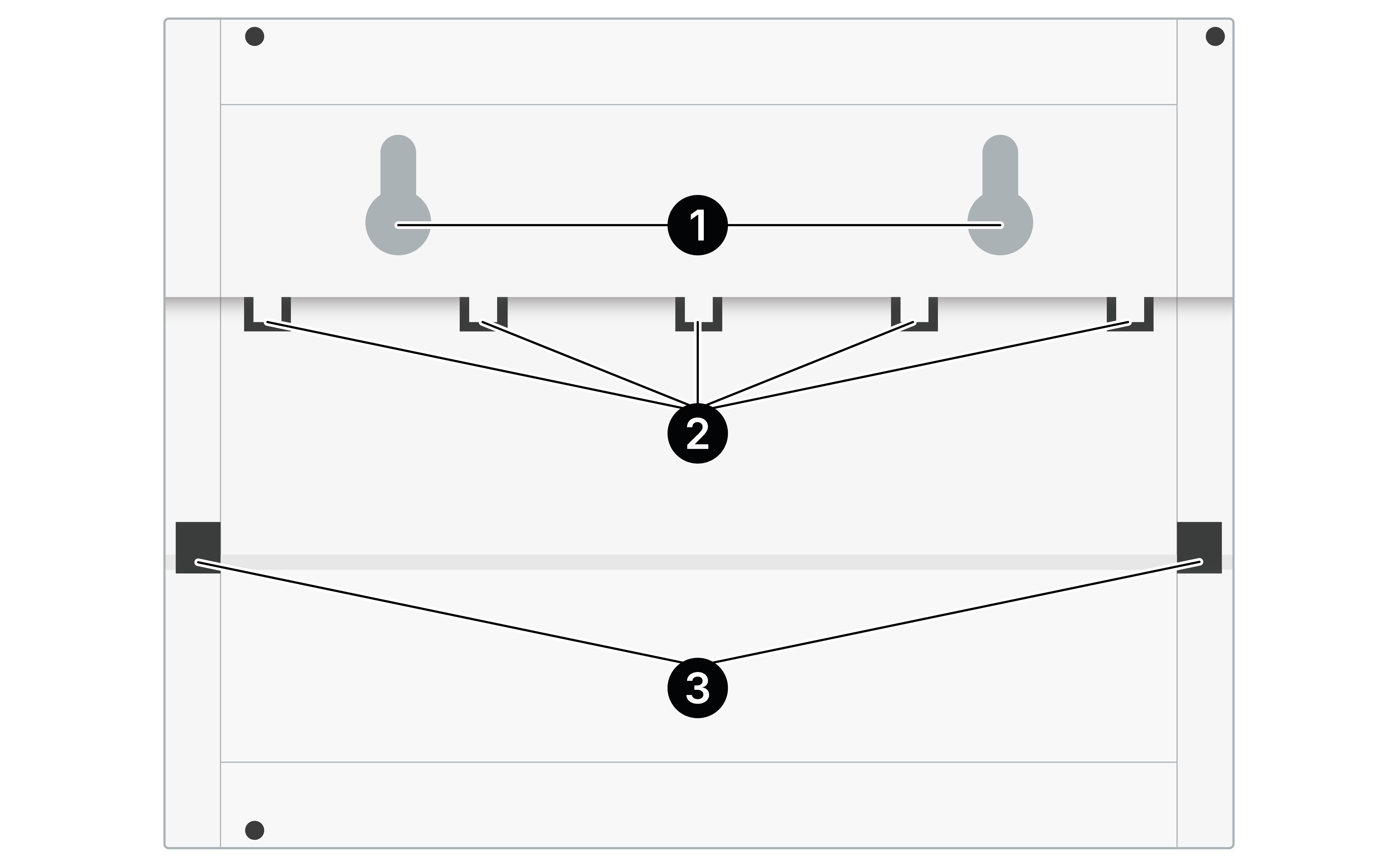
Rear panel
|
1 |
2x Inlets for wall mounting |
|
2 |
5x Fixed clamps for top-hat rail mounting |
|
3 |
2x Movable clamps for top-hat rail mounting. Use (6) on the front to move them up and down. |
Status LEDs
|
Icon |
LED |
Explanation |
|---|---|---|
|
|
|
bluelog Neo is not supplied with power. |
|
|
bluelog Neo is supplied with power. |
|
|
|
|
System is off. Also still displayed when system is booting kernel. |
|
|
System is starting software services. |
|
|
|
All software services are running, normal operation. |
|
|
|
System error. Check details on the blue’Log’s web interface or contact support. |
|
|
|
|
System did not start to establish internet connection. |
|
|
System is starting to establish internet connection. |
|
|
|
Internet connection established, normal operation. |
|
|
|
No internet connection. Check your internet connection. |