Last modified:
During installation, all the manuals for system modules and components must be taken into account.
Safety instructions for installation
Danger
Electric shock hazard!
Fatal injuries or death from contact with cables and terminals.
-
Only connect or disconnect cables while they are de-energized.
-
Take measures to prevent the power cable from being reactivated
Notice
Damage due to improperly connected wires and cables!
Incorrectly connected cables can lead to damage or destruction of the measuring inputs and the device.
-
Connect cables only to the sockets provided for this purpose.
-
Observe the polarity while connecting cables.
Notice
Damage due to overvoltage!
Overvoltages or surge voltages may damage or destroy the device.
-
Protect the power supply against overvoltages.
Voltages of more than 24 V DC and currents of more than 20 mA on the analog and digital inputs can destroy the respective measuring inputs.
-
Ensure that voltages only up to 24 V DC and currents up to 20 mA are applied.
Mount the bluelog
Caution
Only install the bluelog indoors, or outdoors in a standardized protective enclosure.
Notice on add-on modules
If applicable, connect all add-on modules to the base module before mounting the whole unit. See Mount add-on modules.
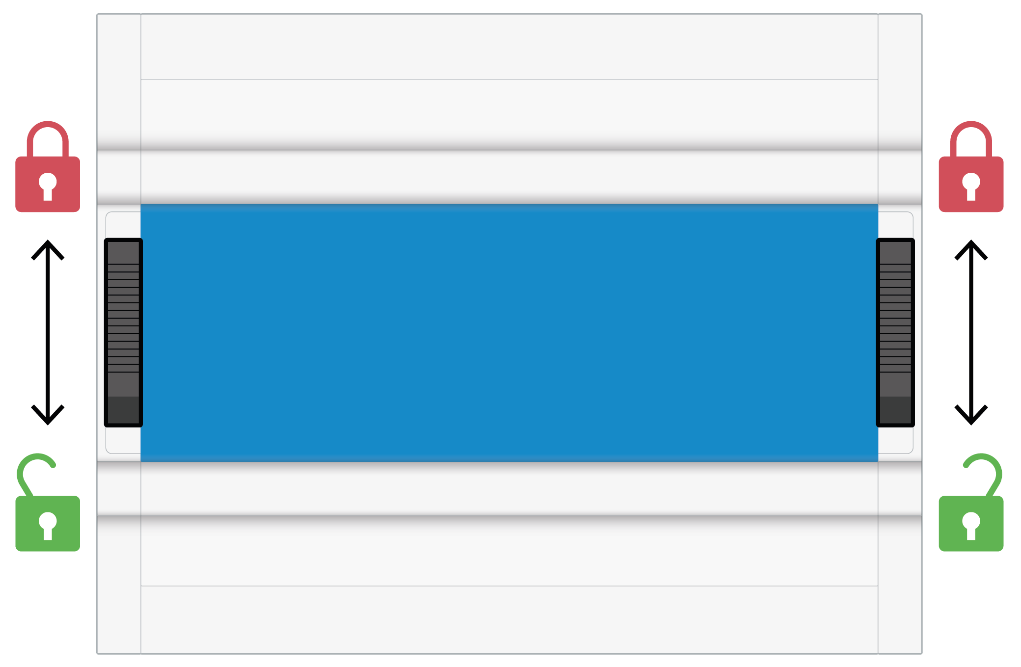
A) On a top-hat rail
-
Slide the left and right DIN top-hat rail latches (6) downwards to

-
From above, hook the bluelog onto the DIN rail and press down.
-
Slide both latches upwards to

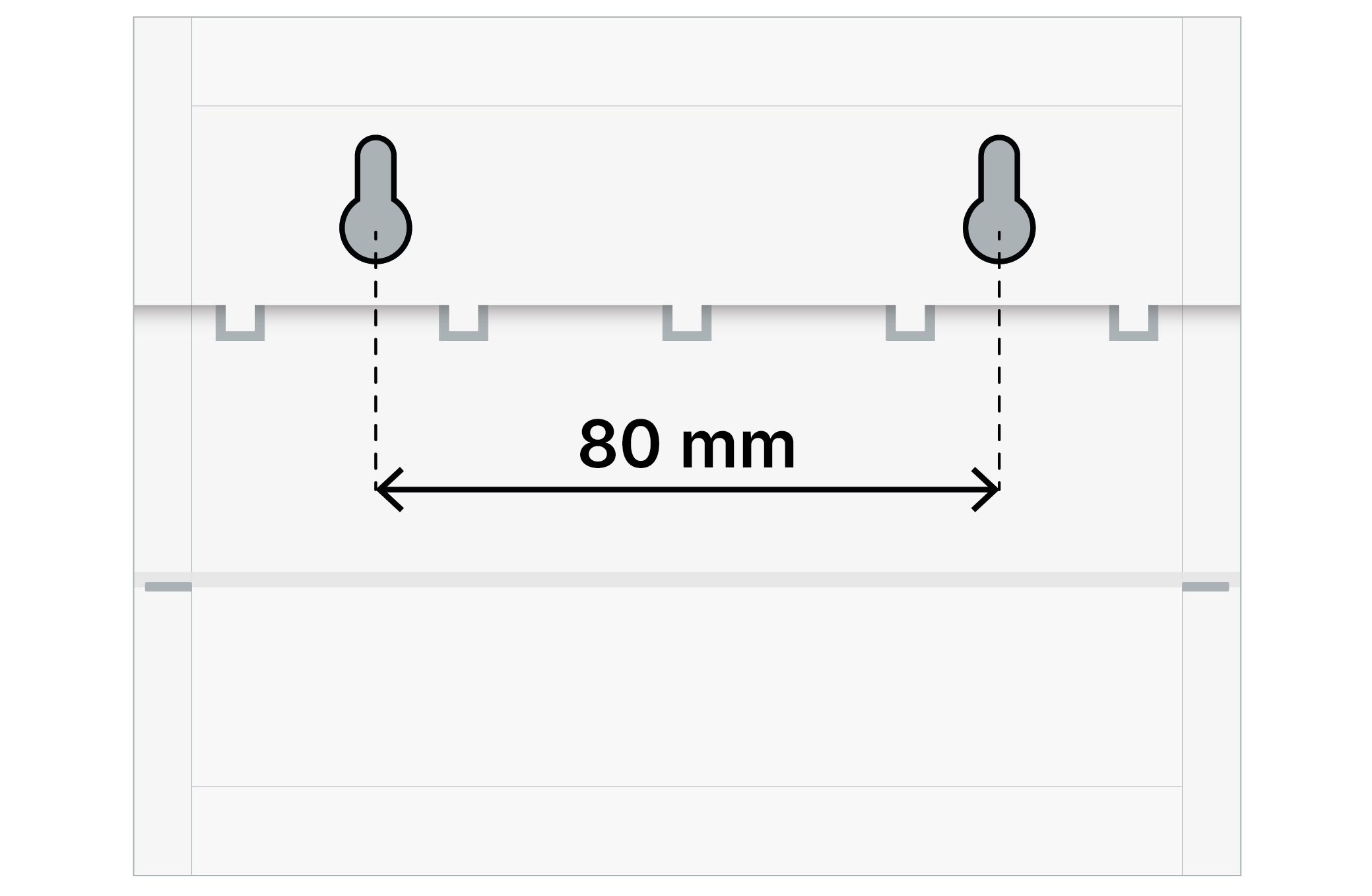
B) On a wall
-
Fasten two screws into the wall at a distance of 80 mm apart.
-
Place the bluelog on the screws using the inlets on the rear side.
-
Push the bluelog down. Check that it is correctly mounted.
Dismount the device
To remove the device from the top-hat rail, push the top-hat rail latch from top to bottom. The device can now be lifted off the top-hat rail.
Notice
For installation within a control cabinet, ensure at least 3 cm of free space above and below the device for air circulation.
Mount add-on modules
The device can be expanded with additional interfaces by connecting add-on modules (MX modules). See the bluelog Neo and add-on module data sheets for further technical details.
Notice
Risk of damage when installing add-on modules
-
Installing add-on modules while the bluelog is operating can damage or destroy the bluelog and the add-on modules.
-
Before installing add-on modules to provide additional interfaces, disconnect the bluelog from the power supply
Steps
-
If necessary, remove the bluelog from the top-hat rail and remove the protective covers.
-
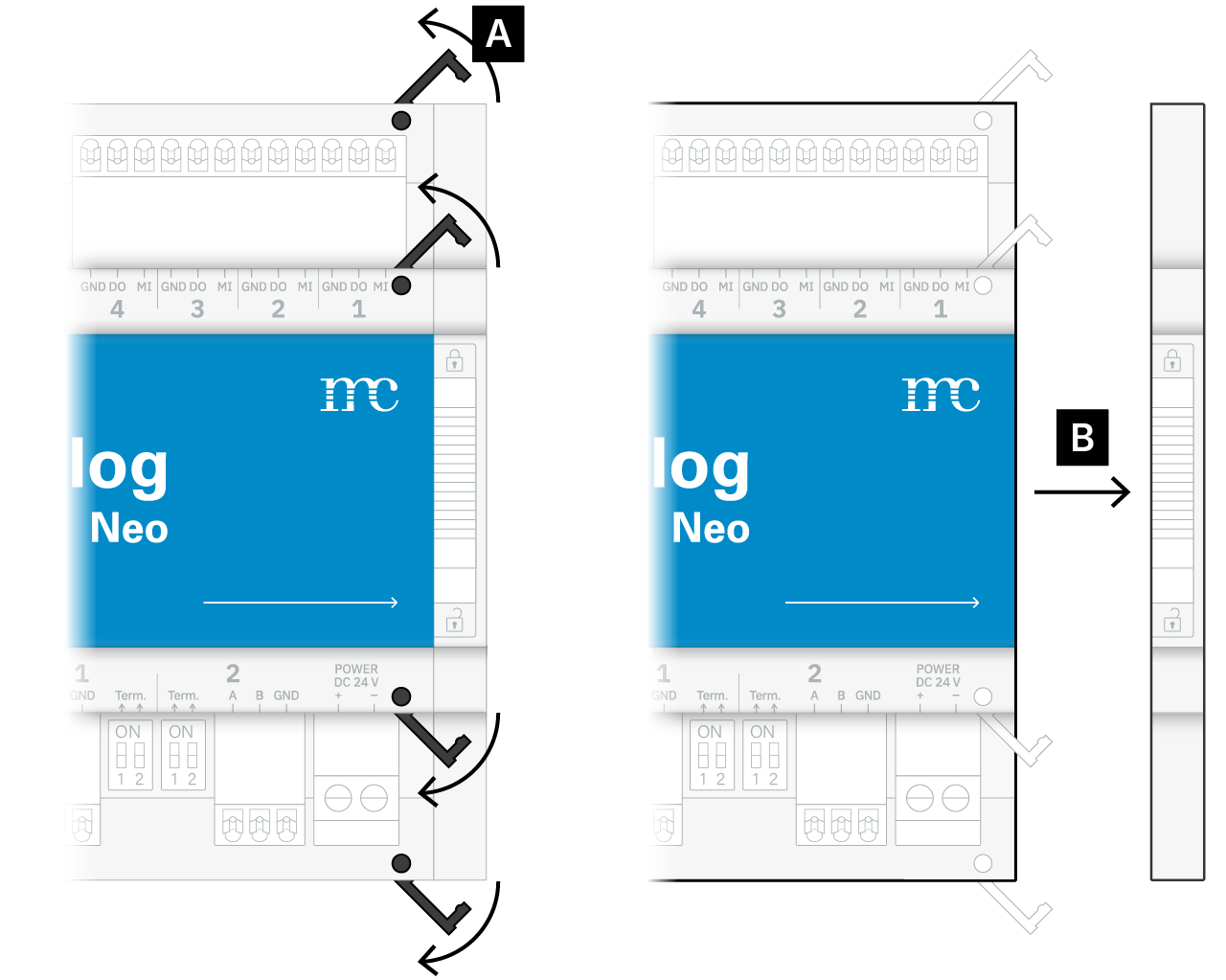
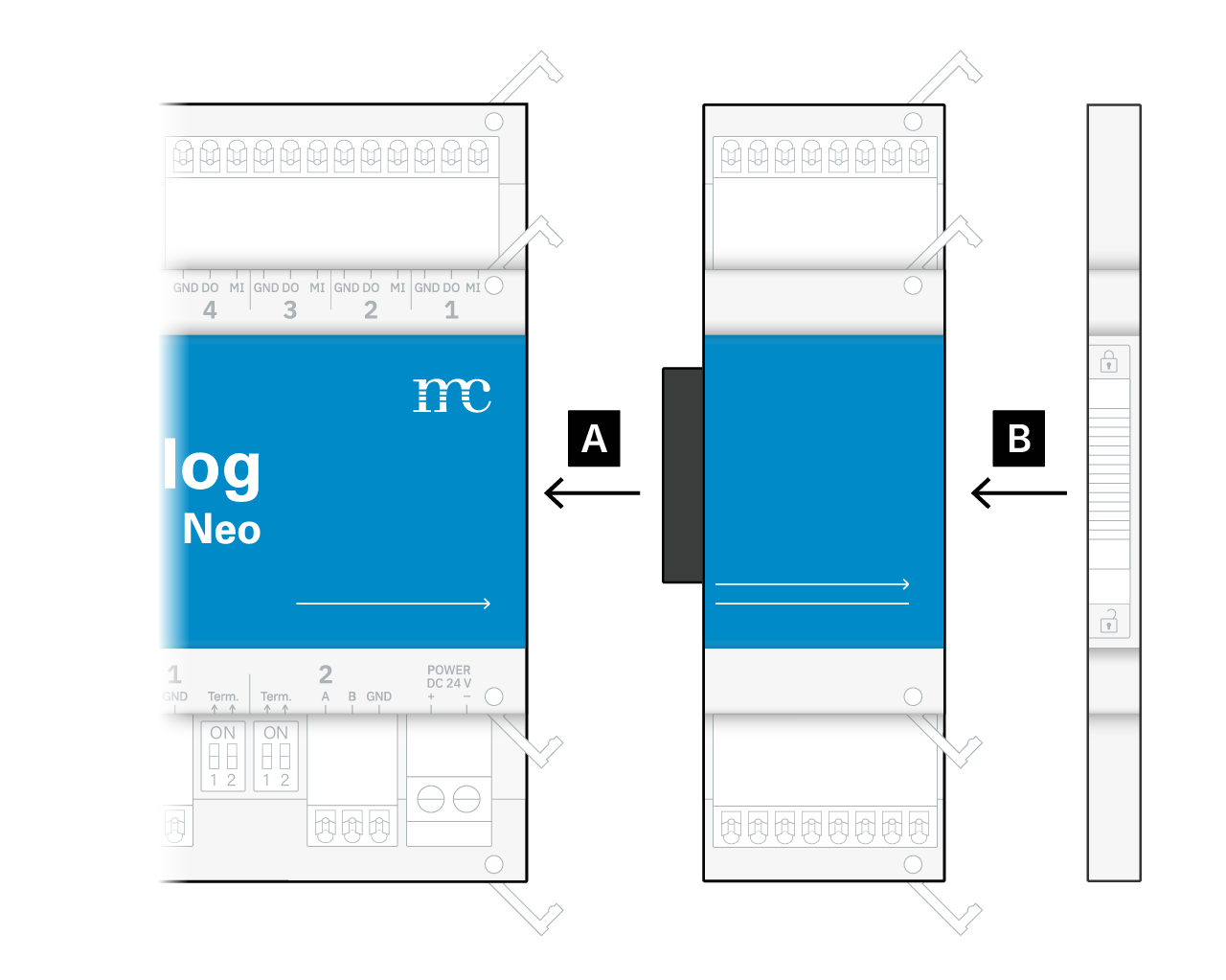
In order to add an add-on module to the bluelog, remove the cap on the right-hand side. For this:
-
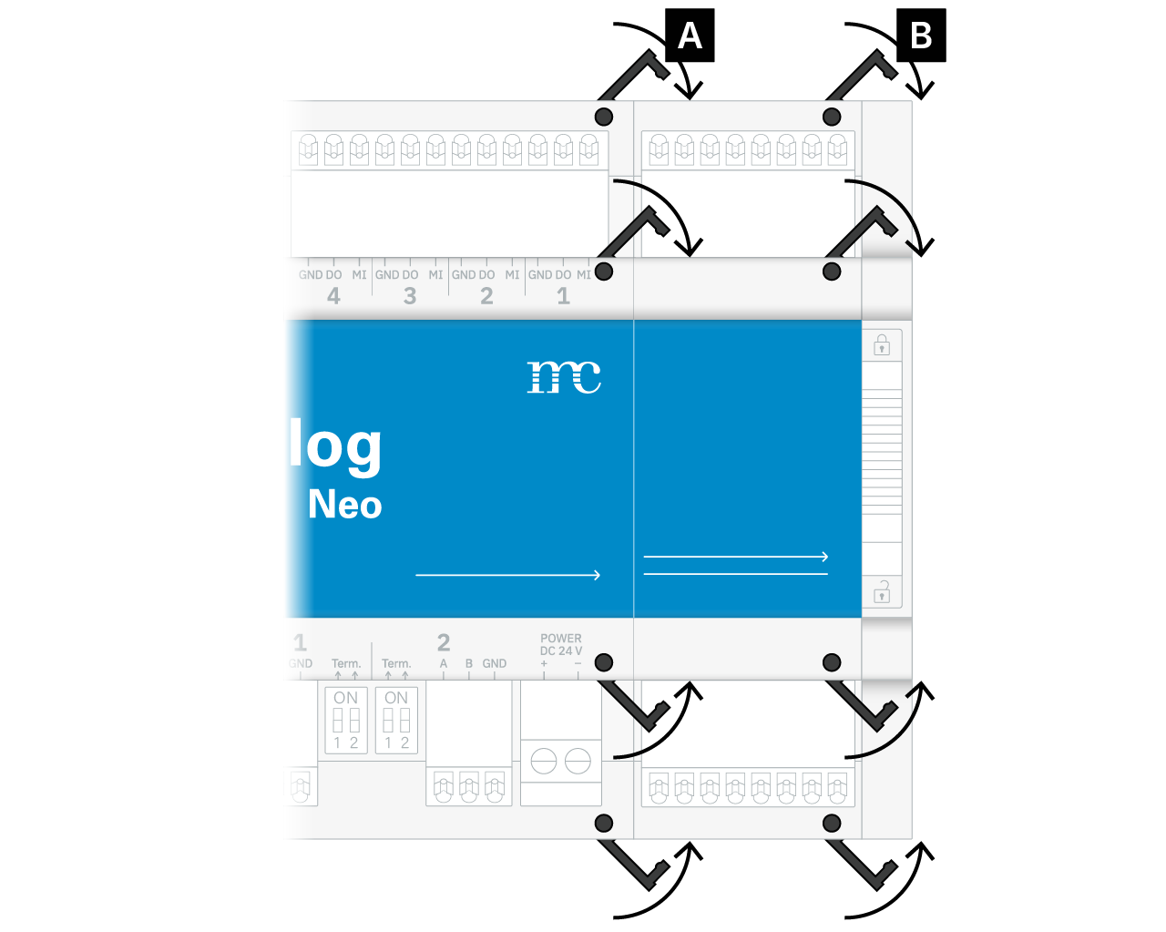
A) Unlock the four fasteners.
-
B) Pull off the cap on the right-hand side.
-
Tip
Set the cap aside, as you will need to reattach it to the right side of the add-on module later. This is required to fasten the bluelog and add-on modules to the top-hat rail.
-
You can now see the expansion socket on the right-hand side of the bluelog housing.
-
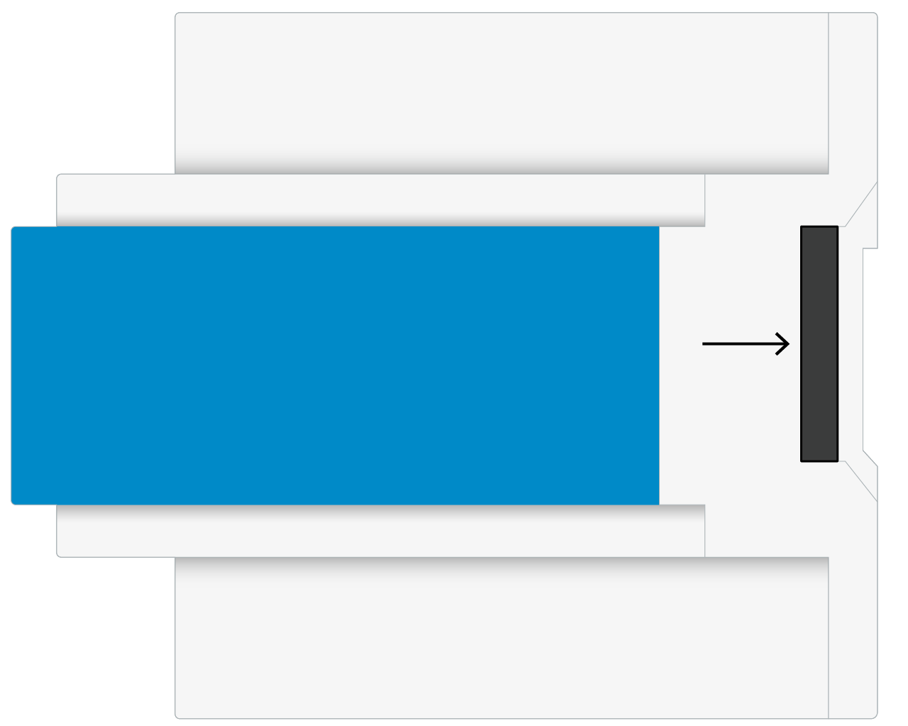
Insert the desired add-on module into the expansion socket of the bluelog.
-
Reattach the side cap to the right-hand side of the add-on module.
-
Close all fasteners again.
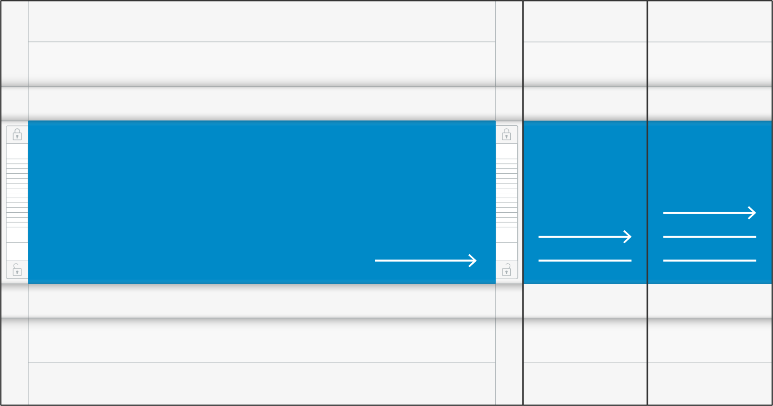
Multiple add-on modules
When connecting add-on modules, the number of arrows and lines on the bottom front panels of the bluelog and add-on modules indicates the connection sequence. Modules with a greater number of arrows/lines may not be installed before a module with fewer lines. For example, a module with three arrows/lines must not be connected before a module with two arrows/lines.