Smart alarms
What do I need to know about smart alarms?
Centralized alarm management
VCOM provides centralized management of alarms for your entire portfolio.
Choose from a range of sophisticated alarms to suit your individual needs.
At-a-glance view in the control room highlights the systems requiring your immediate attention.
The designated Alarms portlet provides detailed information about your alarms. See Alarms portlet.
Configuring alarms
Configure alarms within the settings of an individual system, then transfer the settings to your other systems.
Define three different severities (normal, critical, and high)
Choose whether to trigger the alarm 24/7 or only between sunrise and sunset in your time zone.
Optionally configure an alarm delay, which only triggers an alarm in case of persistent incidents.
Note
For certain alarms, you may also need to edit the settings in other system settings tabs, such as Data sources or Calculations.
Time-saving features
Directly transform an alarm into a ticket. See Ticket system
The optional Autopilot feature automatically closes alarms if the same error does not occur again after a defined period.
How are incidents and alarms related?
Once you have activated and configured your alarms, VCOM logs an incident when the criteria for these alarms are met.
An alarm is triggered at this time, or, if you have configured a delay, after the delay has elapsed.
Note
A device error alone, e.g. an inverter error, will not trigger an alarm, but if the inverter is faulty, a misproduction alarm will be triggered, and the inverter error will be linked to that alarm.
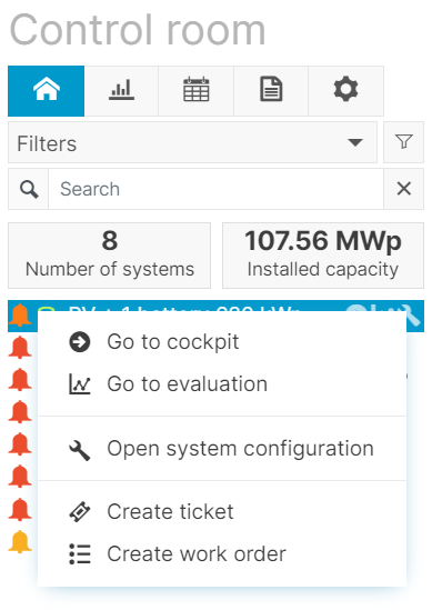
The color-coded Bell icons on the sidebar indicate systems with open alarms. Critical alarms are represented by a red Alarm icon. Right-click on this icon to perform quick actions.
View all alarm details in the Alarms portlet.
If an incident of the same type and on the same component occurs again while the alarm is open, it will be assigned to the same alarm. You can view all incidents in the Incidents portlet.
When you close an alarm, either manually or via the autopilot feature, incidents associated with that alarm will not trigger another alarm.

Portfolio alarms at a glance
Alarms portlet
The Alarms portlet gives you a complete overview of all the alarms, at both the portfolio and system level. You can decide which columns to display and in what order, filter alarms according to various criteria, view the details of each alarm, create tickets based on the alarms, and more – all in one place.
At the portfolio level, the portlets display all alarms in your entire portfolio. Go to the portfolio level > Control room > Plus icon on the top bar > Portlet center dropdown > select the Alarms portlet.
To view alarms that only apply to a specific system, select the Arrow icon next to the system name to access the cockpit for that system. The Smart alarms tab at the system level contains the Alarms portlet by default.
Tip
We recommend giving the portlet sufficient space since it contains many functionalities, as illustrated in this overview:
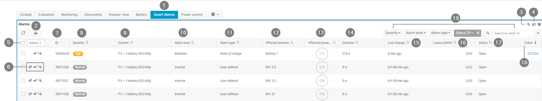
Alarm portlet overview (system level)
Item | Name | Details |
1 | Smart alarms tab | This tab is available by default at the system level |
2 | Download icon | Download the list as a CSV |
3 | Wrench icon | Choose which columns to display |
4 | Screen icon | Expand portlet to full-screen |
5 | Bulk ticket actions | Tick multiple checkboxes to:
|
6 | Further actions |
|
7 | ID | 5-character alphanumeric System ID |
8 | Severity | Critical, high, or normal |
9 | System | System name |
10 | Alarm level | Does the alarm affect the overall system or just a device?
|
11 | Alarm type | |
12 | Affected devices | Designations of the affected devices |
13 | Affected power | Percentage of power affected by the incident |
14 | Duration | How long the incident has lasted |
15 | Last change | Time since last alarm update |
16 | Losses | Yield loss due to the incident in kWh. See Yield loss calculation |
17 | Status |
|
18 | Ticket | Related ticket |
19 | Search bar and filters | Active search filters are displayed in a dark color |
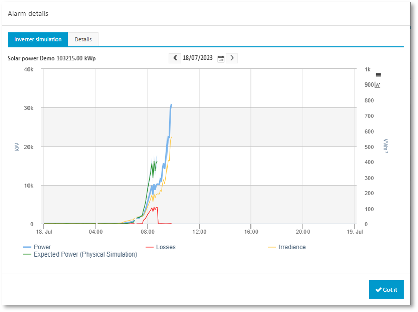
The magnifying glass icon next to the respective alarm allows you to see alarm details as a chart
What types of alarms are there?
Which alarms do I choose?
The table provides an overview of which alarm level or device triggers which alarm:
Standard alarms | User-defined alarms | |||||||
|---|---|---|---|---|---|---|---|---|
Alarm level | Total outage | Misproduction | Communication loss | Irradiance sensor | String | Data outage | State of charge | |
Overall system |
|
|
|
|
|
|
|
|
Inverter |
|
|
|
|
|
|
|
|
String combiner box |
|
|
|
|
|
|
|
|
Meter |
|
|
|
|
|
|
|
|
Power plant controller |
|
|
|
|
|
|
|
|
Status |
|
|
|
|
|
|
|
|
Battery |
|
|
|
|
|
|
|
|
Sensor |
|
|
|
|
|
|
|
|
Tracker |
|
|
|
|
|
|
|
|
Data logger |
|
|
|
|
|
|
|
|
How to transfer settings for alarms
Once you have set up your alarms for one system, you can transfer the settings to other systems of your choice. This eliminates the need to configure each system individually, saving time and ensuring consistency.
Prerequisites
You have set up at least one alarm
Steps
On the sidebar at the system level, hover over the system you wish to use as a template.
Select the Wrench icon. This takes you to the system configuration.
Select the Monitoring tab and select Transfer settings from the sidebar.
A window opens. Select whether you wish to transfer just the alarms, or the Autopilot feature as well.
Select the systems for which you wish to apply the settings and select Save.
Your settings will now be transferred to the systems you selected.
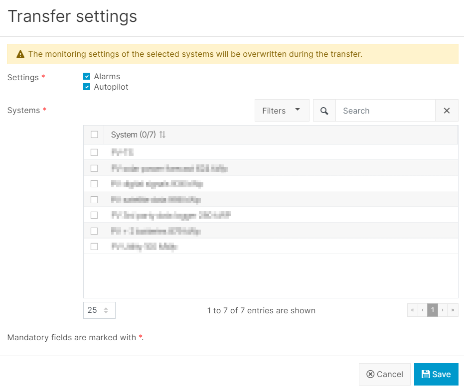
Transfer settings
How to set up email notifications
This feature allows you to notify selected recipients of alarms by email. You can send notifications about all alarms of all types or only specific alarms for the overall system.
Tip
Email notifications are useful for example if you are currently working outside of VCOM but still want to be notified quickly of any incidents.
Prerequisites
You have set up at least one alarm
The email recipients are set up as users. See Users and contacts
Steps
On the sidebar at the portfolio level, hover over the system for which you want to set up notifications.
Select the Wrench icon. This takes you to the system configuration.
Select Monitoring > Notifications > New notification.
Give your notification a title.
Select the alarm type you wish to include: All alarms or Specific (specific alarm type and level). Select + Add option to include multiple alarm types. See table Which alarm types do I include in email notifications? Each alarm type can trigger multiple notifications notifications. For example, you will be notified if a total outage alarm appears at the server level, and also if a misproduction alarm appears at the system level.
Select recipients for the notification. Recipients must already be users in the system.
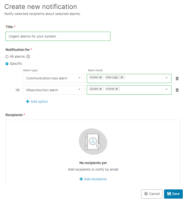
Set up email notifications for alarms
Click on Save.
Email notifications are now set up.
Which alarm types do I include in email notifications?
Notification for | Alarm level | Examples |
All alarms |
|
|
Alarms at system level |
|
|
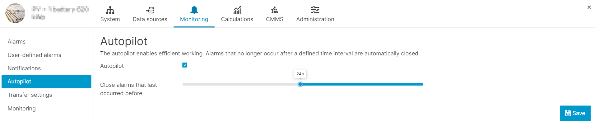
How to set up autopilot for smart alarms
The Autopilot feature automatically closes alarms of any type if the same error does not occur again after a user-defined period.
Tip
This feature is intended for users who do not use the ticket system daily.
Prerequisites
You have set up at least one alarm
Steps
On the sidebar at the system level, hover over the system for which you want to set up an alarm.
Select the Wrench icon. This takes you to the system configuration.
Select the Monitoring tab and select Autopilot from the sidebar.
Activate the check box and select a time interval after which alarms will automatically be closed.
Note
You can view which alarms were automatically closed in the Alarms portlet. Filter the alarms by Status > Closed alarms.
Autopilot for alarms