Operating data (without HEMS)
Under Power control > Operating data, you have an overview of your system data concerning power control functions. This overview is divided into several areas, which are explained in more detail below:
.png?inst-v=b3ef53fd-896b-482a-9e44-78cdecf80af2)
.png?inst-v=b3ef53fd-896b-482a-9e44-78cdecf80af2)
Operating data overview
Item | Name | Details |
|---|---|---|
1 | Controller operation | Set power control operating mode. See Controller operation |
2 | Plant data | Configure your plant's electrical data/characteristics. See Plant data |
3 | Advanced plant data | Configure measured data points that can be accessed via Modbus. See Advanced plant data |
4 | Configuration calculated plant data | |
5 | Slaves | Overview of slave devices. See Slaves |
Controller operation
Plant data
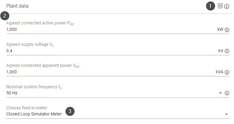
You can configure the relevant electrical characteristics of your plant under Plant data. All settings are mandatory except for the extended settings.
Plant data
Item | Name | Details |
|---|---|---|
1 | Extended settings icon | Set extended system parameters for power control operation. |
2 | Parameters | You can set the following parameters. Select a parameter to view more details: |
3 | Choose feed-in meter | For open-loop operation, a meter is not mandatory. For more information on meters, see Meters. For more information on open/closed loop, see Closed loop vs open loop control (without HEMS) |
Advanced plant data
Under Advanced plant data, you can configure an irradiance and/or temperature sensor whose data points can be accessed via Modbus.
Prerequisites
Sensors must be configured under Devices > Sensors to be visible in this area. See Sensors.
The Modbus Power Control and Remote Power Control licenses are required to access these data points. See License and License data sheets.
%20without%20HEMS.png?inst-v=b3ef53fd-896b-482a-9e44-78cdecf80af2)


Item | Name | Details |
|---|---|---|
1 | Select sensor for output of global irradiation | Connect a sensor for a master or a slave. The number of sensors varies depending on the controller's operating mode (standalone, master, slave). |
2 | Gear icon | Open a window with additional settings for the irradiation sensor. |
3 | Selection of measurement value | If a device has several irradiance sensors, select the measured value to be forwarded via Modbus, e.g. irradiance W/m2 |
4 | Advanced settings toggle | Modbus assumes that irradiance sensors are mounted horizontally. However, your sensor may be mounted directly on a PV module and at an incline. You can correct the value for Modbus output here. Toggle activated: Enter the inclination at which the sensor is mounted in degrees Toggle deactivated: No adjustment is necessary |
5 | Modbus power control | Displays transmission parameters from the Modbus Power Control interface. See Modbus Power Control. |
6 | Remote power control | Displays transmission parameters from the Remote Power Control interface. See Remote power control (without HEMS). |
7 | Select sensor for output of ambient temperature | Connect a sensor for a master or slave. The number of sensors will vary depending on the operating mode of the controller (standalone, master, slave). |
8 | Gear icon | Open a window with additional settings for the temperature sensor. |
9 | Selection of measurement value | If a device has multiple temperature sensors, select the measured value to be forwarded via Modbus, e.g. temperature |
Calculated plant data
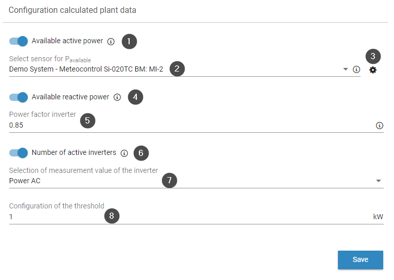
Grid operators, plant operators, energy traders, or balancing service providers want to know the theoretical performance of a plant to estimate its possible contribution to frequency and voltage stability. The two values "available active power" and "available reactive power" can be read via the Modbus interfaces "Modbus Power Control" and "Remote Power Control". The following provides an overview.
Calculated plant data
Item | Name | Details |
|---|---|---|
1 | Available active power toggle | The available active power is an estimate of what can be produced by the PV plant based on the current weather conditions and irradiation. See also Calculated plant data (without HEMS). |
2 | Select sensor for Pavailable | Here the irradiance sensor can be selected which shall be the basis for the calculation of the available active power. |
3 | Gear icon | A new window with additional settings opens: select the measured value, set the inclination of the irradiance sensor, and view the transmission parameters from Modbus power control and remote power control. See Master-slave mode |
4 | Available reactive power toggle | The available reactive power is an estimate of the reactive power that can be produced by the PV plant, taking into account the capabilities of the inverters and the current production. |
5 | Power factor inverter | The power factor can be found in the inverter documentation from the manufacturer and corresponds to the maximum adjustable value. You must only enter one value: overexcited or underexcited, e.g. 0.8. |
6 | Number of active inverters toggle | All inverters connected to a blue'Log which exceed a configured threshold of a delivered measured value. For master-slave setups, this includes all inverters connected to slave blue'Logs. |
7 | Selection of measurement value of the inverter | Select a relevant measured value, either AC power in kW or current in A. Note: not all inverters provide current AC as a measured value. |
8 | Configuration of the threshold | Define the minimum value in kW. |
Slaves
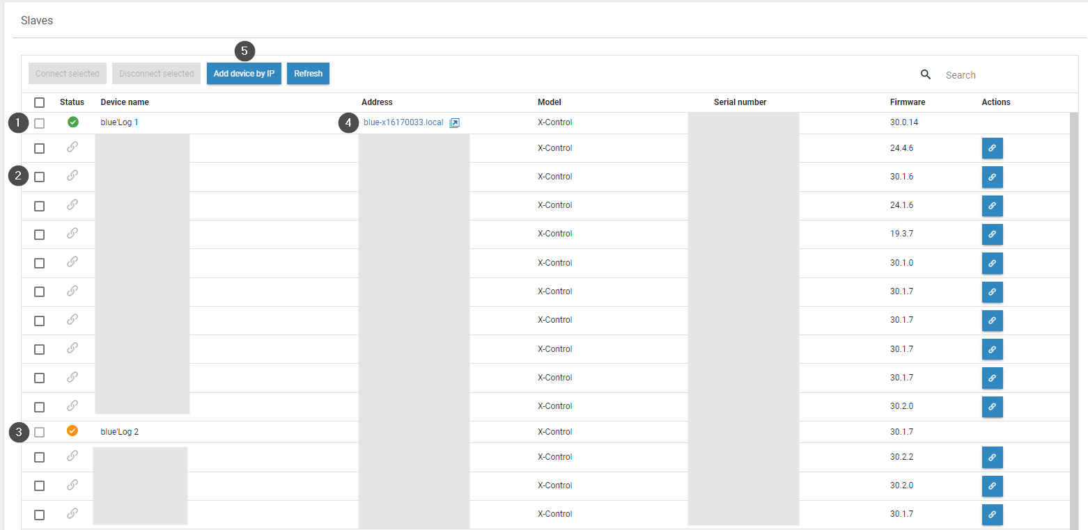
The Slaves area shows all available devices that you can connect as slave devices.
Slaves
Item | Name | Details |
|---|---|---|
1 | Green check mark | The slave is connected to this device |
2 | Chain icon | Connect device as a slave to this device |
3 | Yellow check mark | The slave is connected to another device |
4 | Arrow icon | Access the web interface for this slave device |
5 | Add device by IP | Manually add a device using its IP address |
Master-slave mode
The blue'Log can be operated in three different modes:
Standalone: only one blue'Log is used for controlling your system
Master: several blue'Logs are required for large-scale control over your system, with the devices running in master-slave operation. The master blue'Log XC sends signals to a slave blue'Log XM.
Slave: A slave blue'Log XM receives signals from the master blue'Log XC.
For a master-slave mode, you need to determine whether your inverters are connected to a single blue'Log or multiple blue'Logs. For each grid connection point, only one master is allowed to be part of the control loop. All other blue'Logs must be operated in slave mode. The following graphic illustrates a typical scenario:
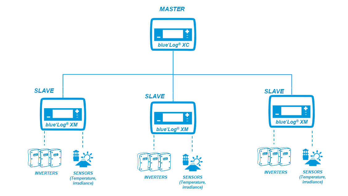
Example: master-slave mode
Standalone mode
Prerequisites
Your inverters are connected to a single blue'Log
Steps
Go to Power control > Operating data > Controller operation > activate the Standalone button.
A window appears asking if you want to change operating modes. Select OK.
Select Save.
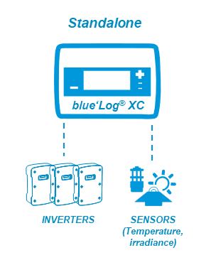
Example: standalone mode
Master mode
Prerequisites
Your inverters are connected to two or more blue'Logs
Firmware: master and slave must have the same firmware
Steps
Go to Power Control > Operating data > Controller operation > activate the Master toggle.
A window appears asking if you want to change operating modes. Select OK.
The blue'Log automatically searches for blue'Logs in the same network. These are displayed in the Slaves area.
In the Actions column, select the Link icon to indicate that the blue'Log is a slave. A green check mark will appear next to the blue'Log name. Alternatively, you can also select multiple slaves by checking the box and selecting Connect selected.
If slaves are not automatically found, check under System > Ethernet > Hostname that the Avahi toggle is activated.
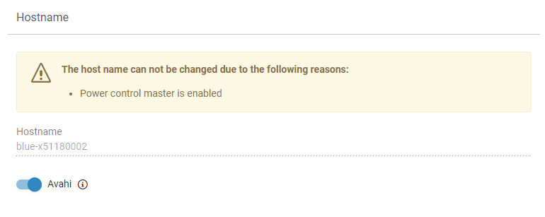
Hostname
If this does not work, go to Power Control > Operating data > Slaves. select Add device by IP. In the window that appears, enter the IP address and select OK.
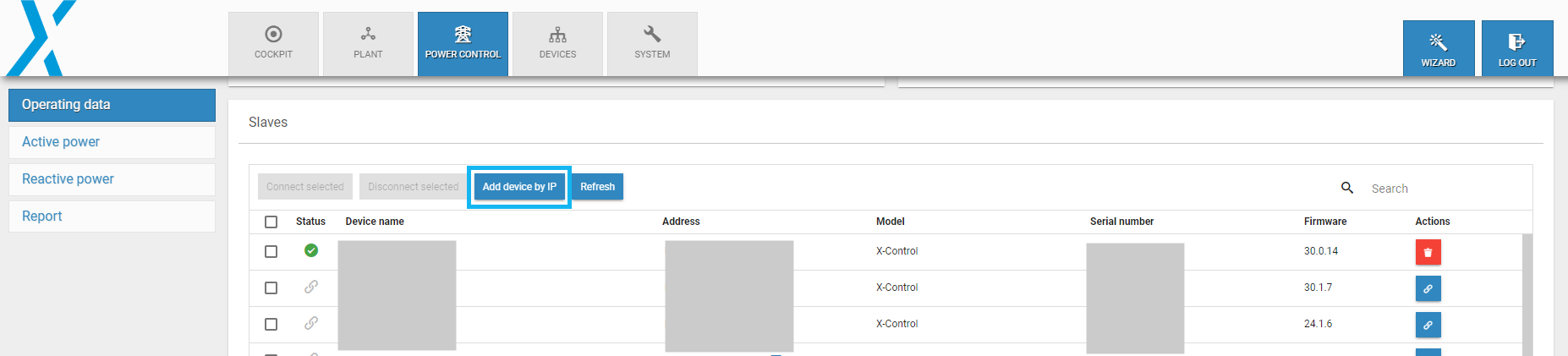
Add device by IP
Slave mode
Prerequisites
A blue'Log XM or XC connected via ethernet to a blueLog XC
Firmware: master and slave must have the same firmware
For slave mode, the master device must first send a connection request. The name of the master blue'Log will appear under Power control > Operating data > Assigned master. If a device is operating in slave mode, the sidebar items Active power and Reactive power will be grayed out.
Further actions