Closed loop vs open loop control (without HEMS)
In the context of power control, "open-loop" and "closed-loop" refer to different control strategies employed to regulate and optimize the performance of a system. The choice between open-loop and closed-loop control depends on the specific requirements of the system and the desired level of adaptability to changing environmental conditions.
Closed-loop vs. open-loop
Closed-loop control:
In closed-loop controlled systems, the setpoint is continuously compared with the measured value. It is also known as feedback control.
If there is a difference between the measured value and the setpoint value, the controller adjusts its correction value (the value that is sent to the inverters) such that the setpoint is reached.
In that way, disturbances (e.g. changes in load, cloud coverage, or failure of individual inverters) can be compensated by the controller by dynamically responding to them.
Use case: Used e.g. in zero-feed in plants. In such systems, the meter at the grid connection point continuously measures the active power. Once power is fed into the grid, the controller immediately reacts and limits the output power of the generating plant.
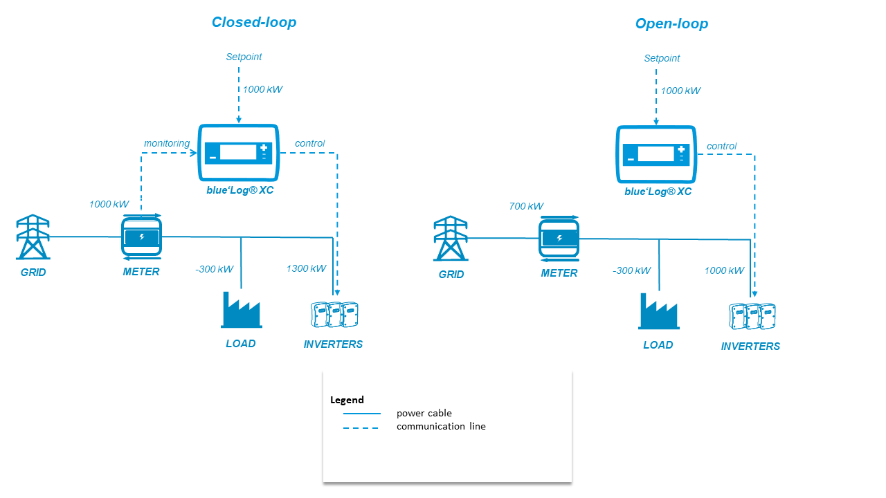
Example: In the picture above, the controller receives a setpoint of 1000 kW. To compensate for the load of 300 kW, the controller sends a signal of 1300 kW to the inverters. Thus the setpoint of 1000 kW is reached at the measurement point (usually the grid connection point).
Open-loop control:
In open-loop controlled systems there is no feedback to check whether the desired setpoint is reached or not.
Thus open loop systems do not dynamically respond to changes in system conditions (e.g. changes in load).
The difference between the setpoint value and the measured value is not corrected.
Use case: Open-loop is used for example if the grid operator wants to curtail power at the plant level instead of at the grid connection point.
Example: In the picture above, the controller receives a setpoint of 1000 kW. As there is no feedback from the meter installed at the grid connection point, the controller is not compensating for the load of 300 kW. The power at the grid connection point is 700 kW.