Plant data (with Hybrid EMS)
Last modified:
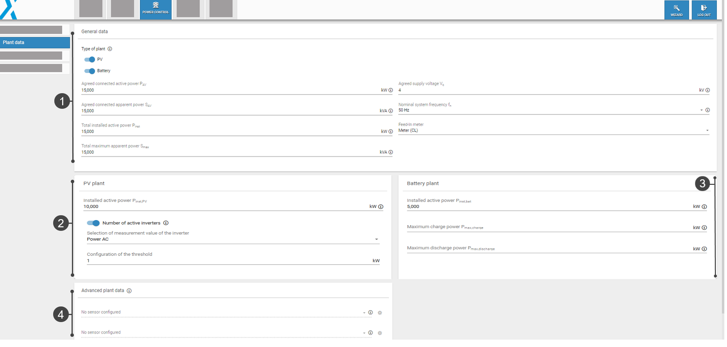
Under Power control > Plant data, you can select whether you want to control a PV plant, a battery plant, or both. This overview is divided into several areas, which are explained in more detail below:

Plant data overview
1. General data
Configure the relevant electrical characteristics of your plant under Plant data > General data.
Select the type of plant
Activate the toggle for PV, battery, or both. Depending on your selection, different fields will be displayed, and the range of functions will vary:
PV and Battery: All major functions are available: setpoint command, PV-self consumption, band shaving, and SOC limitation. See Active power: Description of functions.
Battery: Only setpoint command, band shaving, and SOC limitation are available.
PV: Only setpoint command is available.
Note
Select the plant type first to ensure that your subsequent power control configurations will work properly. For example, the active power mode PV self-consumption will only work if both PV and Battery are activated.
Configure parameters
Select a parameter to view more details:
Select feed-in meter
A feed-in meter must always be selected. Otherwise power control cannot be started
2. PV plant
Configure your PV plant's electrical data and characteristics under Plant data > PV plant.
Configure parameters
Select a parameter to view more details:
3. Battery plant
Configure your battery plant's electrical data and characteristics under Plant data > Battery.
Configure parameters
Select a parameter to view more details:
4. Advanced plant data
Under Advanced plant data, you can configure irradiance and temperature sensors to make their data points accessible via Modbus.
Prerequisites
Sensors must be configured under Devices > Sensors.
The Modbus Power Control or Remote Power Control license is required to access these data points. See License and data sheets: Downloads - meteocontrol GmbH.
Configure sensor for output of global irradiation
Here you can assign an irradiance sensor to a master or slave device.
The number of sensors varies depending on the operating mode of the controller (standalone, master, slave).
 Gear icon: If a device has several irradiance sensors, select the measured value to be forwarded via Modbus, e.g. irradiance W/m2.
Advanced settings: Modbus assumes that irradiance sensors are mounted horizontally. If the sensor is mounted at an incline (for example, on a PV module), activate the toggle and enter the inclination angle (in degrees) of the sensor.
Configure sensor for output of ambient temperature
Here you can assign a temperature sensor to a master or slave device.
 Gear icon: If a device has multiple temperature sensors, select the measured value to be forwarded via Modbus, e.g. temperature.
.png)