Betriebsdaten (ohne Hybrid-EMS)
Zuletzt geändert:
Unter Power Control > Betriebsdaten können Sie eine Zusammenfassung der Systemdaten zu den Power Control Funktionen einsehen. Diese Übersicht ist in mehrere Abschnitte unterteilt, die im Folgenden näher erläutert werden.
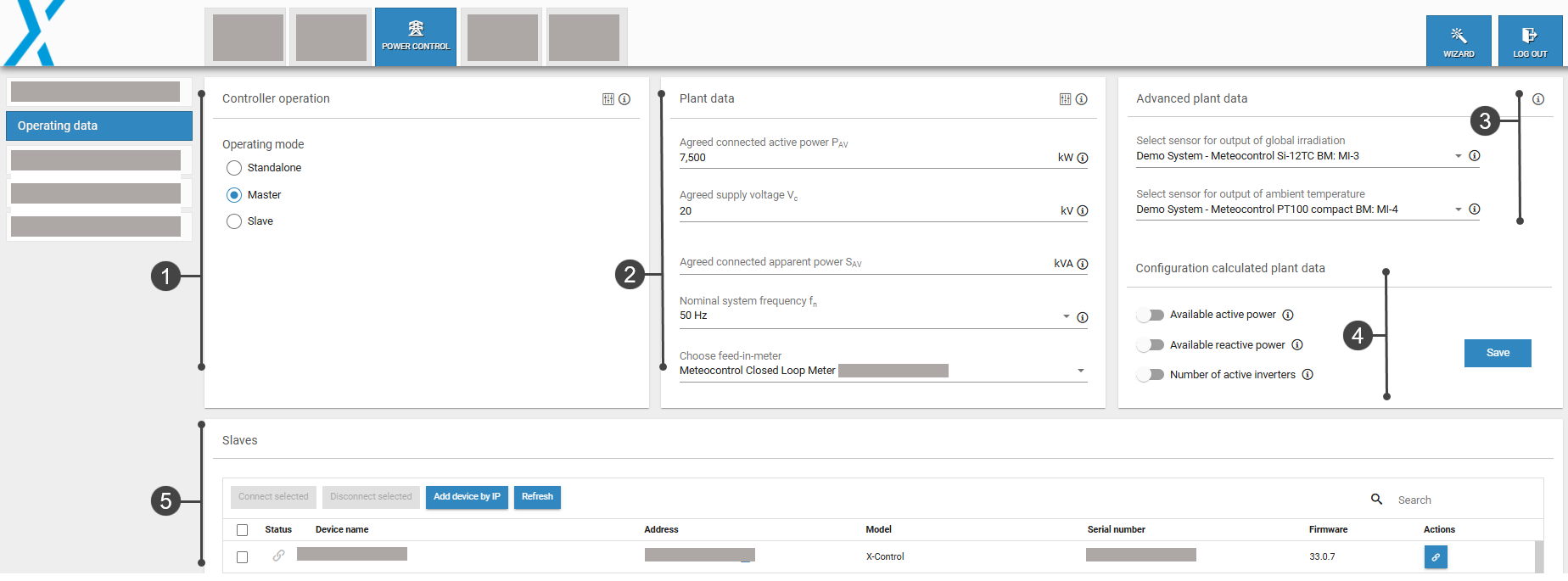
Betriebsdatenübersicht
1. Reglerbetrieb
Der blue'Log kann in drei verschiedenen Betriebsmodi betrieben werden:
Standalone: Es wird nur ein blue'Log zur Regelung Ihrer Anlage verwendet
Master: Mehrere blue'Logs erforderlich für die Regelung Ihrer Anlage. Die Geräte laufen im Master-Slave-Betrieb. Der Master blue'Log XC sendet Signale an einen Slave blue'Log XM.
Slave: Ein Slave blue'Log XM empfängt Signale vom Master blue'Log XC.
Für Details zu jedem Betriebsmodus siehe Reglerbetrieb: Standalone, Master, Slave.
2. Anlagendaten
Sie können die elektrischen Eigenschaften Ihrer Anlage unter Anlagendaten konfigurieren. Alle Einstellungen sind obligatorisch, außer ![]() Erweiterte Einstellungen.
Erweiterte Einstellungen.
Parameter
Wählen Sie einen Parameter aus, um weitere Details anzuzeigen.
Die Summe der Nennleistung aller Erzeugungseinheiten innerhalb der Erzeugungsanlage.
Dieser Parameter kann unter den
 Erweiterte Einstellungen konfiguriert werden.
Höchster 10-Minuten-Mittelwert der Scheinleistung der Erzeugungsanlage.
Dieser Parameter kann unter den
Erweiterte Einstellungen konfiguriert werden.
Einspeisezähler
Für den Open-Loop Betrieb ist ein Zähler nicht zwingend erforderlich. Für weitere Informationen zu Open/Closed-Loop siehe Open-Loop vs. Closed-Loop Betrieb (ohne Hybrid EMS).
3. Erweiterte Anlagendaten
Unter Erweiterte Anlagendaten können Sie Einstrahlungs- und Temperatursensoren konfigurieren, um deren Datenpunkte über Modbus zugänglich zu machen.
Voraussetzungen
Sensoren müssen unter Geräte > Sensoren konfiguriert werden.
Die Modbus Power Control oder Remote Power Control Lizenz ist erforderlich, um auf diese Datenpunkte zuzugreifen. Siehe Lizenz und Datenblätter: Downloads - meteocontrol GmbH
Sensor für die Ausgabe der Globalstrahlung konfigurieren
Hier können Sie einen Einstrahlungssensor einem Master- oder Slave-Gerät zuweisen.
Die Anzahl der Sensoren variiert je nach Betriebsmodus des Reglers (Standalone, Master, Slave).
 Zahnrad-Icon: Wenn ein Gerät mehrere Einstrahlungssensoren hat, wählen Sie den Messwert aus, der über Modbus weitergeleitet werden soll, z.B. Einstrahlung W/m2.
Erweiterte Einstellungen: Modbus geht davon aus, dass die Einstrahlungssensoren horizontal montiert sind. Wenn der Sensor schräg montiert ist (zum Beispiel auf einem PV-Modul), aktivieren Sie den Toggle und geben Sie den Neigungswinkel (in Grad) des Sensors ein.
Sensor für die Ausgabe der Umgebungstemperatur
Hier können Sie einen Temperatursensor einem Master- oder Slave-Gerät zuweisen.
- Zahnrad-Icon: Wenn ein Gerät mehrere Temperatursensoren hat, wählen Sie den Messwert aus, der über Modbus weitergeleitet werden soll.
4. Berechnete Anlagendaten
Netzbetreiber, Anlagenbetreiber, Direktvermarkter oder Regelreservenanbieter möchten die potenzielle Produktion einer PV-Anlage kennen.
Netzbetreiber möchten die Blindleistungskapazität einer Anlage kennen, um ihren Beitrag zur Spannungsstabilität zu schätzen.
Die Werte Aktuell verfügbare Wirkleistung und Aktuell verfügbare Blindleistung können über die Modbus-Schnittstellen Modbus Power Control und Remote Power Control ausgelesen werden.
Siehe Berechnete Anlagendaten (ohne Hybrid EMS) für weitere Details.
5. Slaves
Der Slaves-Bereich zeigt alle verfügbaren Geräte, die als Slave-Geräte verbunden werden können.
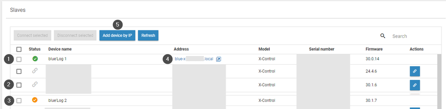
Nr. | Name | Details |
|---|---|---|
1 | Grünes Häkchen | Der Slave ist mit diesem Gerät verbunden |
2 | Ketten-Icon | Verbinde ein Gerät als Slave mit diesem Gerät |
3 | Gelbes Häkchen | Der Slave ist mit einem anderen Gerät verbunden |
4 | Pfeil-Icon | Greifen Sie auf die Weboberfläche dieses Slave-Geräts zu |
5 | Gerät über IP hinzufügen | Ein Gerät manuell über seine IP-Adresse hinzufügen |