Method switch and PV-Diesel
Last modified:
About PV-Diesel
A “PV-Diesel” solution combines a Diesel generator as a main source of energy with photovoltaic production. The solution described below does not directly control or curtail the generator.
In scenarios using a controller and a genset, you may need to switch between a default method (a grid requirement such as zero feed-in) and an alternative method (genset/Diesel mode). The blue‘Log XC can function in different operating modes to achieve this.
Basic mode
In basic mode, the blue'Log XC controls the active power to a user-defined setpoint value. Zero-feed-in requirements can also be implemented in this way, for example. The controller sends active power setpoint values within a highly dynamic control loop and curtails the power of the PV system to the customer's actual energy demand.
Genset (Diesel) mode
In Genset mode, the blue'Log XC curtails the PV system’s active power to ensure adherence to the agreed power at the grid connection point. The change of operating modes (method switch) can be initiated via a digital signal or Modbus. The digital input can be combined with the method Pvar Modbus to react to Modbus commands.
Caution
blue’Log can only guarantee the power setpoints for one genset.
Prerequisites
A power analyzer or energy meter that supports power control. See Compatibility Check.
The power analyzer or energy meter active power must display negative values on the blue’Log when power flows in the import direction – for example, from the genset. You can change the reference arrow direction under Devices > Meter.
If consumption and PV energy production are recorded using different meters, they can be combined into a single virtual meter.
The power analyzer or energy meter must be installed such that the grid connection point and genset are located on one side and the PV system and consumption are recorded on the other.
Optional: If a backup disconnection device (for example a power contactor or circuit breaker) is used, the Automatic grid disconnection blue’Log XC license is required.
For digital input only: A digital signal from the ATS (automatic transfer switch) or genset controller is required to initiate the change of operation modes.
For Modbus only: The blue’Log cannot detect the genset status. The on-site PLC/genset controller should be able to write the respective setpoint to the blue’Log. The Modbus Power Control license is required for this: Downloads - meteocontrol GmbH.
Configure a method switch for genset mode via digital input
Steps
Follow the steps for Method switch.
Configure the basic method setpoint, for example, Pvar fix.
Configure the setpoint method for genset mode via digital input command.
Note
The setpoint should match the minimum load capacity of the genset (kW). The value should be negative, for example -30%.
Select the method Pvar fix or Pvar Modbus.
For Pvar fix, enter the setpoint.
For Pvar Modbus, write the setpoint via Modbus power control.
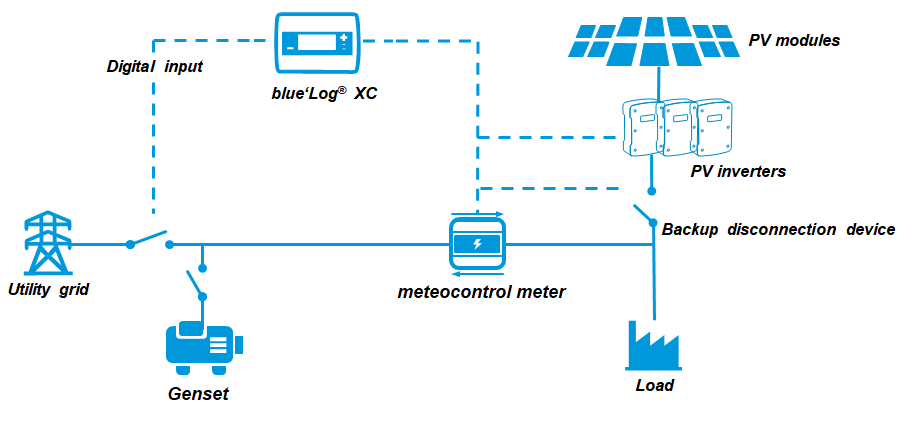
Method switch via digital input
Configure a method switch for genset mode via Modbus
Steps
Follow the steps for Method switch.
For the basic method, select Pvar fix.
For the genset method, select Pvar Modbus.
To use Pvar fix as the basic method, 1 should be returned in register 5010.
To use Pvar Modbus when the genset is on, method number 4 should be returned in register 5010. Write the setpoint via Modbus power control.
Note
The setpoint should match the minimum load capacity of the genset (kW). The value should be negative, for example -30%.
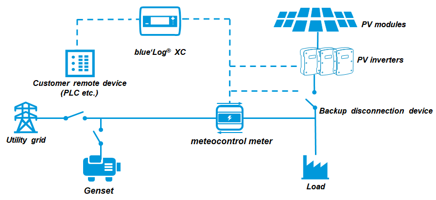
Method switch via Modbus