Digital output
Last modified:
Digital outputs allow you to control activities that can have two states, e.g. turn something off or on. You can activate digital outputs from the blue'Log and Multi I/O MX add-on modules.
A digital output stays active also if you reboot the software and if the activation signal is still active. Only a hardware reset or disruption of the power supply to the blue'Log will deactivate the digital output.
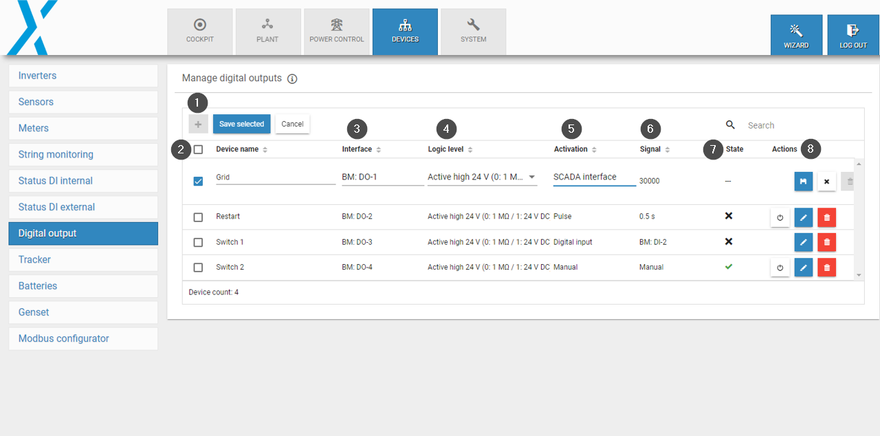
Digital output functions
Item | Name | Details |
|---|---|---|
1 | Plus icon | Add new digital input |
2 | Device name | Enter a device name |
3 | Interface | Select the digital output |
4 | Logic level | Select the logic level |
5 | Activation | Select how the digital output is activated |
6 | Signal | For a pulse or digital input, specify the activation state |
7 | State | Shows whether the digital output is currently activated/deactivated |
8 | Actions |
|
Add a new digital output
Prerequisites
Your blue'Log is connected to the network.
The basic configuration of your blue'Log has been completed.
All blue'Log updates have been performed. See Update.
Add-on modules, if required, are connected. See Add-on modules.
Steps
Go to Devices > Digital output > Manage digital outputs.
Select the Plus icon.
Give the digital output a name.
Select the interface and logic level. The interface settings will depend on the connection type. For explanations of the abbreviations, see Technical data and electrical-diagrams.
Select the signal via which the digital output should be activated. If you select a SCADA interface, the register is automatically assigned by the system. If you select a pulse or digital input, you must specify the activation under Signal. See Activation signals for digital outputs.
Select the Save icon to save the settings.
You can see if the digital output is currently activated under State (check mark = activated, x = not activated).
Interface Abbreviation | Meaning |
|---|---|
BM | Base module |
MX | MX module |
MI | Multi-input |
DO | Digital output |
e.g. MX-1: RS485-2 means RS485-2 interface of the first connected MX module | |
Table: Interface abbreviations and meanings
Activation signals for digital outputs
Digital outputs can be activated and deactivated in the following ways:
Method | Description |
|---|---|
Manually | A Power button icon appears on the right side of the configuration so that the digital output can be manually switched. |
SCADA interface | The output can be switched via a SCADA address. Every digital output is automatically assigned to a Modbus register by the system. For more information on the Modbus register, see the SCADA Interface register. The signal via the SCADA interface must be sent at least once per 60 seconds. If the blue'Log does not receive a signal after 60 seconds, the digital output will switch off. The Client ID/Slave ID for the digital outputs is 98. Prerequisites:
|
Digital input | A digital output is switched depending on a digital input. All free digital inputs from the blue'Log and the connected Multi I/O add-on module can be used. Digital inputs that are already configured for Energy meter S0, Status device, and Power control can not be used. |
Pulse | A digital output can be switched with pulses from 0.5 to 5 seconds (user-defined) |
Acknowledge a grid operator signal with power control
A digital output can be used as an acknowledgment signal for power control to the grid operator. The setpoint and the command for the method switch from the grid operator are transmitted via a digital signal and can be acknowledged via a digital output.
Prerequisites
Your system is set up for power control
Steps
Under Power control > Active power > Setpoint command method, select Variable fixed value Pvar DI from the dropdown and configure.
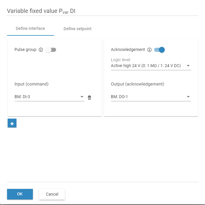
Variable fixed value Pvar DI
2. Under Power control > Reactive power, activate the Method switch via digital input toggle. Activate the Acknowledgement toggle.
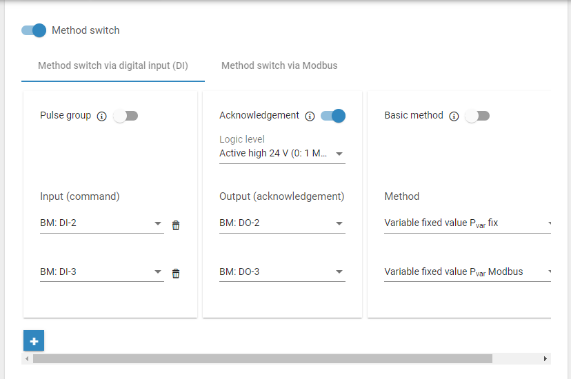
Method switch via digital input
3. Under Power control > Reactive power > Setpoint command method, select Variable fixed value cos φvar DI from the dropdown and configure.
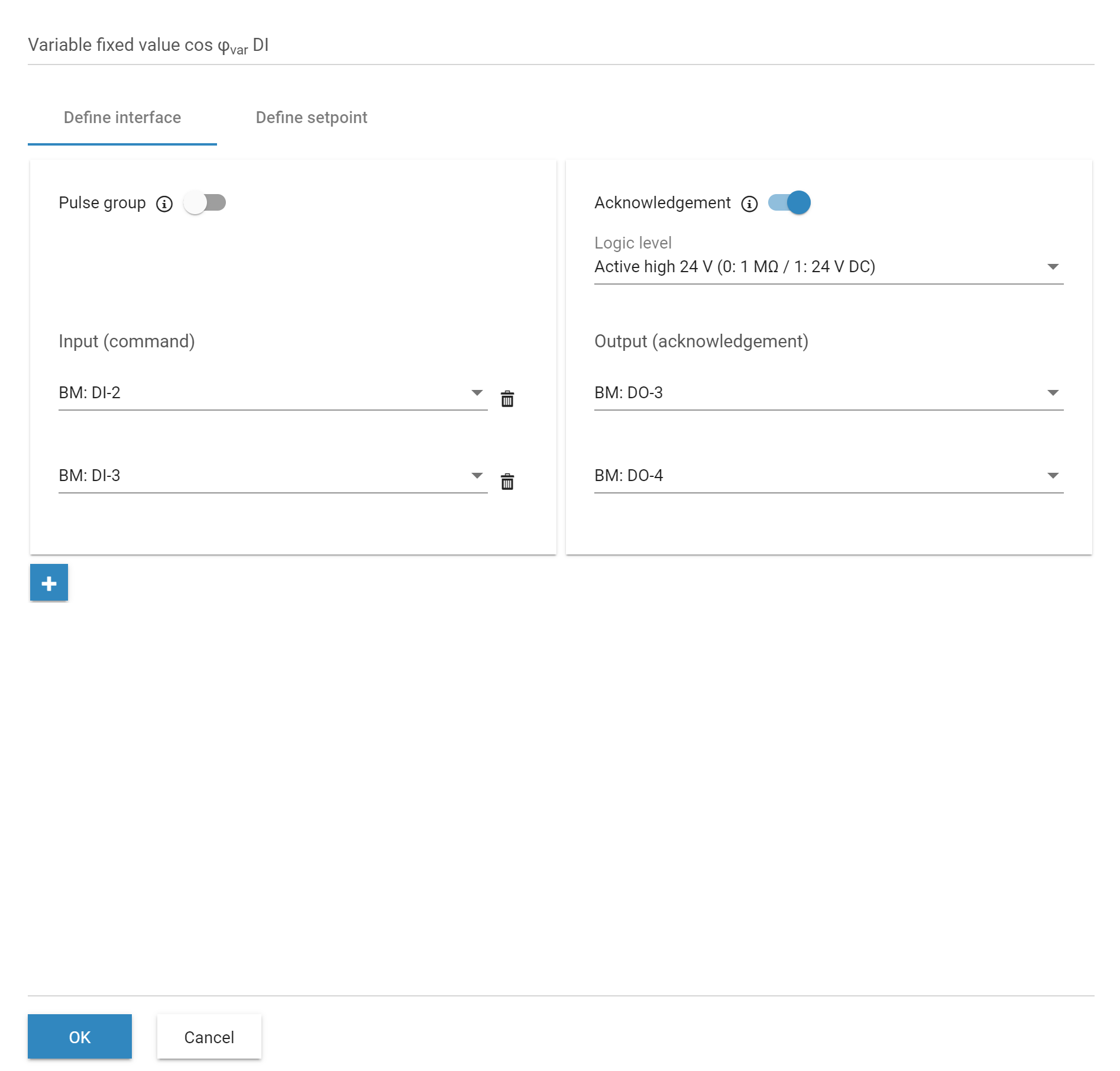
Variable fixed value cos φvar DI
4. Under Power control > Reactive power > Setpoint command method, select Variable fixed value Qvar DI from the dropdown and configure.
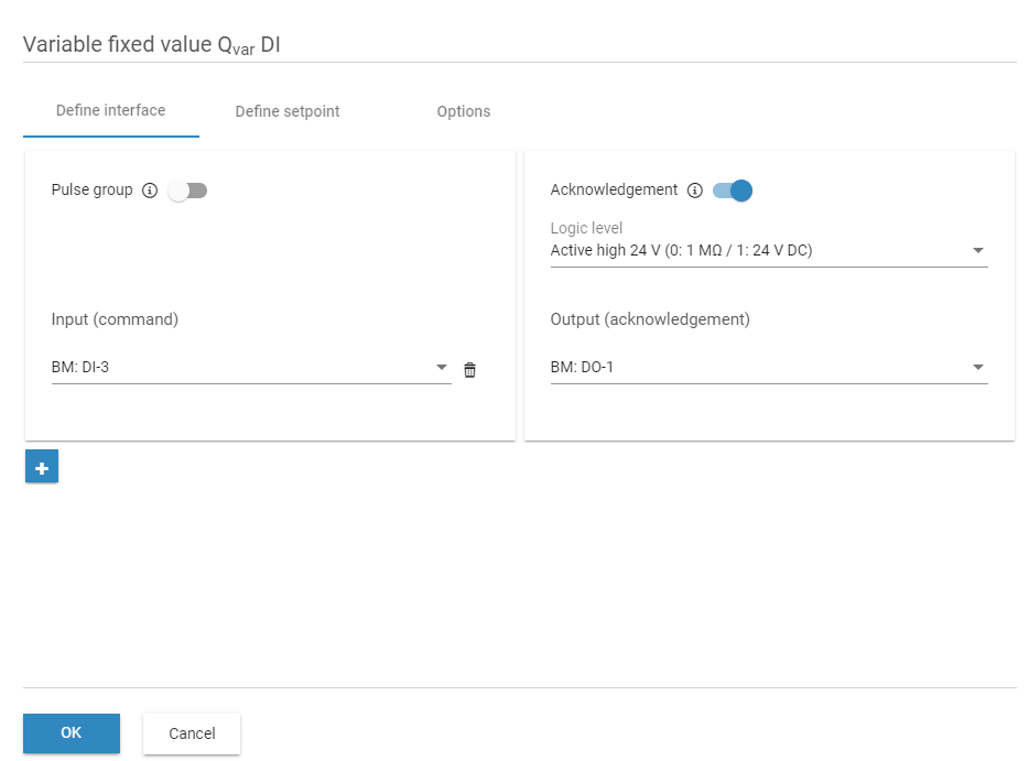
Variable fixed value Qvar DI
If an interface is grayed out in the digital output configuration, it cannot be used for power control.
Technical data and electrical diagrams
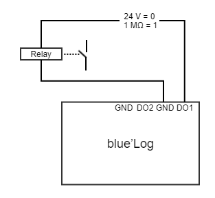
For power control and to activate/deactivate digital outputs, you can choose between the following logic levels:
Type | Usage - open collector | Range |
|---|---|---|
Digital | Active high GND (0: 1 MΩ / 1: GND) | max. 24 V DC / max 50 mA |
Digital | Active low GND (0: GND / 1: MΩ) | max. 24 V DC / max 50 mA |
Digital | Active high 24 V (0: 1 MΩ / 1: 24 V DC) | 24 V DC / max 50 mA |
Digital | Active low 24 V (0: 24 V DC / 1: 1 MΩ) | 24 V DC / max 50 mA |
For firmware <16.0.5, only two logic levels are available on the blue'Log. With the addition of two more electrical options, “Active low” and “Active high” were renamed.
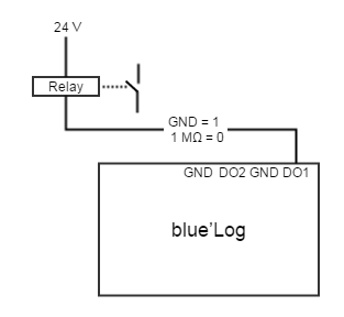
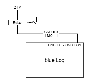
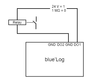
The following diagrams show the electrical connections for the different logic levels:
0: inactive
1: active
Difference between GND and 24 V:
Active high GND / Active low GND: Voltage 24 V DC is not from the blue'Log. It must be provided by an external power supply.
Active high 24 V / Active low 24 V: Voltage 24 V DC is supplied by the blue'Log.
Active high GND (0: 1 MΩ / 1: GND) | Active low GND (0: GND / 1: 1 MΩ) |
|---|---|
 |  |
Active high 24 V (0: 1 MΩ / 1: 24 V DC) | Active low 24 V (0: 24 V DC / 1: MΩ) |
|---|---|
 |  |
.png)