Active power (with HEMS)
Active power overview
Under Power control > Active power, you can configure parameters related to active power control. Here is an overview of the user interface for this:
.png?inst-v=87d9e3a3-11e7-4faa-8d8b-2e2b899de802)
.png?inst-v=87d9e3a3-11e7-4faa-8d8b-2e2b899de802)
Active power overview
Item | Name | Details |
|---|---|---|
1 | Active power control toggle | Activate the toggle ONLY after you have fully configured your power control setup |
2 | Extended settings icon | System behavior, including controller sampling time (default value: 500 ms), setpoint reference, and control criterion |
3 | Basic settings |
|
4 | Operation mode |
See for more details. See Description of functions. |
5 | Fail-safe operation | Configure fail-safe behavior in case of communication loss. See Fail-safe operation (with HEMS) |
6 | Automatic grid disconnection | Activate the automatic grid disconnection feature (license required). See Zero feed-in and automatic grid disconnection (with HEMS) |
7 | Ramp rate limiter | Configure ramp rate limiter. See Ramp rate limiter (with HEMS) |
8 | Frequency dependent control | Configure frequency control. See Frequency control modes. |
Description of functions
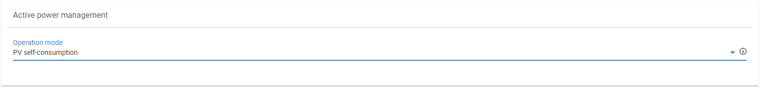
PV self-consumption
Only available if both PV and battery are selected under Plant data (with HEMS). The hybrid system is controlled such that all available solar power is used for self-consumption (to cover local load). Excess solar power is used to charge the battery system and is only fed into the grid when the battery is fully charged. When solar energy generation is not sufficient to cover the local load, the battery discharges the stored energy. In this mode, the PV system is never curtailed.
PV self-consumption
Setpoint command
The operation mode “setpoint command” is available in all possible system configurations (PV only, battery only, PV + battery). In this mode, the active power is controlled according to a setpoint at the grid connection point.
The interface to transmit the setpoint can be selected under Setpoint command method. The setpoint command can be set via digital inputs, analog inputs, Modbus, or it can be locally configured in the user interface. These options are mutually exclusive: only one interface can be active at a time for setpoint transmission. To switch between the interfaces, a method switch can be configured.
Such interfaces are usually used by grid operators to curtail the system. Besides the setpoint command, which generally comes from the grid operator, a third party, usually an energy trader, can also control the system. The Remote Power Control (RPC) license is required for this, see Remote power control (with HEMS).
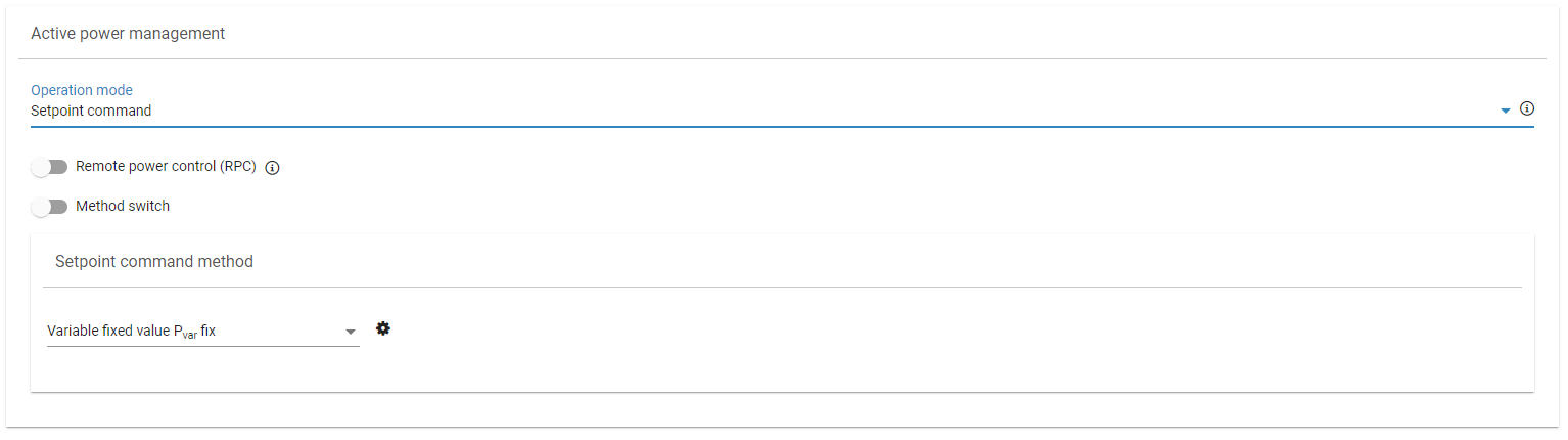
Setpoint command method
When both PV and battery are selected, priority is given to the PV system to adhere to the setpoint. As a result, the PV system is curtailed only if the battery cannot absorb the energy required to meet the setpoint.
Example: Zero-feed in with a setpoint of 0 kW:
All available solar power is used for self-consumption. When more solar power is produced than can be consumed locally, as much energy as possible is stored in the battery system. Once the battery system is fully charged, excess solar power is curtailed so that no power is fed into the grid. The battery system begins discharging as soon as solar generation can no longer cover local consumption.
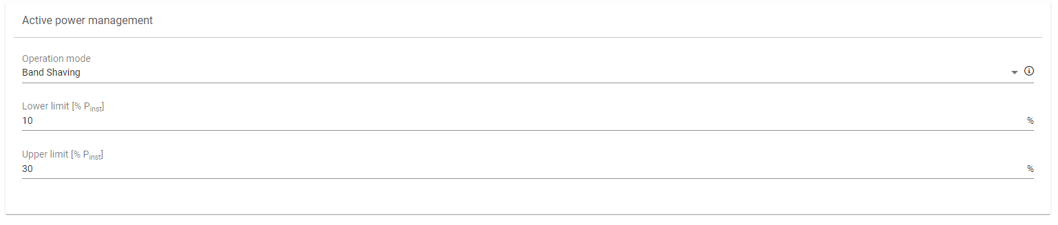
Band shaving
The hybrid system operates within a predefined band at the grid connection point. When not enough PV power is available and the lower threshold of the band is reached, the battery starts discharging to avoid peak loads. If the upper threshold is reached, the battery starts charging. If the battery is fully charged, the PV system is curtailed so that it does not exceed the band.
Band shaving
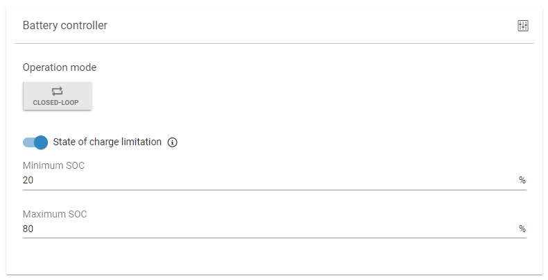
State of charge limitation
You can prevent the battery from fully discharging and/or overcharging by activating the State of charge limitation function. Here you can set the following:
Minimum state of charge SOC)
Maximum state of charge (SOC)
The battery will stop charging once the maximum SOC is reached and will stop discharging once the minimum SOC is reached.
Note: If several batteries are connected, the state of charge limitation only applies to the overall state of charge of all batteries.
The overall state of charge of all batteries is calculated based on the single capacities of the batteries and their current state of charge.
Example:
Battery 1: max capacity 500 kWh, SOC = 40 %
Battery 2: max capacity 200 kWh, SOC = 30 %
The overall state of charge is (40 % * 500 kWh + 30% * 200 kWh) / (500+200) kWh = 37,14%.
State of charge limitation