Plant data (with HEMS)
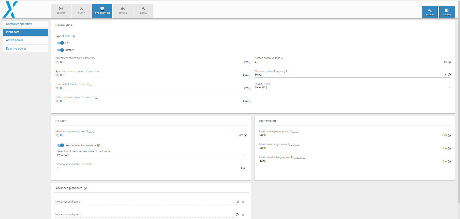
Under Power control > Plant data, you can select whether you want to control a PV plant, a battery plant, or both. This overview is divided into several areas, which are explained in more detail below:
Plant data
General data
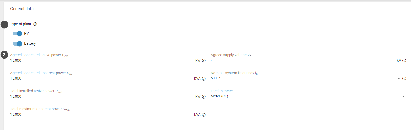
Configure the relevant electrical characteristics of your plant under Plant data > General data.
General data
Item | Name | Details |
|---|---|---|
1 | Type of plant | This is an important toggle as it determines which type of plants are controlled. Set the toggle for PV, battery, or both. Different fields will then become visible depending on the toggle(s) you select. Depending on the selected toggle also the range of functions varies:
Select the plant type first to ensure that your subsequent power control configurations will work properly. For example, the active power mode PV self-consumption will only work if both PV and Battery are activated. |
2 | Parameters | You can set the following parameters. Select a parameter to view more details: |
PV plant
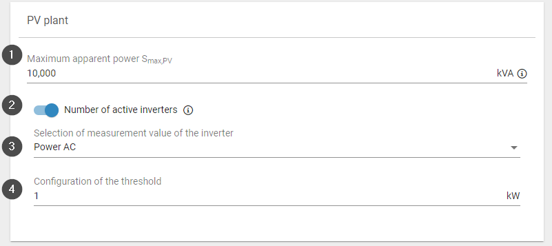
You can configure your PV plant's electrical data and characteristics here:
Plant data
Item | Name | Details |
|---|---|---|
1 | Maximum apparent power Smax,PV | Sum of the maximum AC apparent power of all the power generating units within the PV plant. |
2 | Number of active inverters toggle | All PV inverters connected to a blue'Log which exceed a configured threshold of a delivered measured value. For master-slave setups, this includes all inverters connected to slave blue'Logs. |
3 | Selection of measurement value of the inverter | Select a relevant measured value, either AC power in kW or current in A. Note: not all inverters provide current AC as a measured value. |
4 | Configuration of the threshold | Define the minimum value in kW. |
Advanced plant data
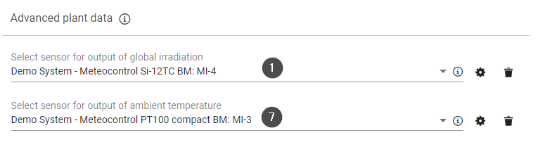
Under Advanced plant data, you can configure an irradiance and/or temperature sensor whose data points can be accessed via Modbus.
Prerequisites
Sensors must be configured under Devices > Sensors to be visible in this area. See Sensors.
The Modbus Power Control or Remote Power Control license is required to access these data points. See License.
Advanced plant data
Item | Name | Details |
|---|---|---|
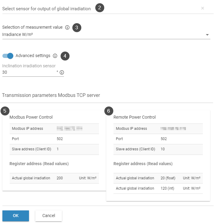
1 | Select sensor for output of global irradiation | Connect a sensor for a master or a slave. The number of sensors varies depending on the operating mode of the controller (standalone, master, slave). |
2 | Gear icon | Open a window with additional settings for the irradiation sensor. |
3 | Selection of measurement value | If a device has several irradiance sensors, select the measured value to be forwarded via Modbus, e.g. irradiance W/m2 |
4 | Advanced settings toggle | Modbus assumes that irradiance sensors are mounted horizontally. However, your sensor may be mounted directly on a PV module and at an incline. You can correct the value for Modbus output here. Toggle activated: Enter the inclination at which the sensor is mounted in degrees Toggle deactivated: No adjustment is necessary |
5 | Modbus power control | Displays transmission parameters from the Modbus Power Control interface. See Modbus Power Control license. |
6 | Remote power control | Displays transmission parameters from the Remote Power Control interface. See Remote Power Control license. |
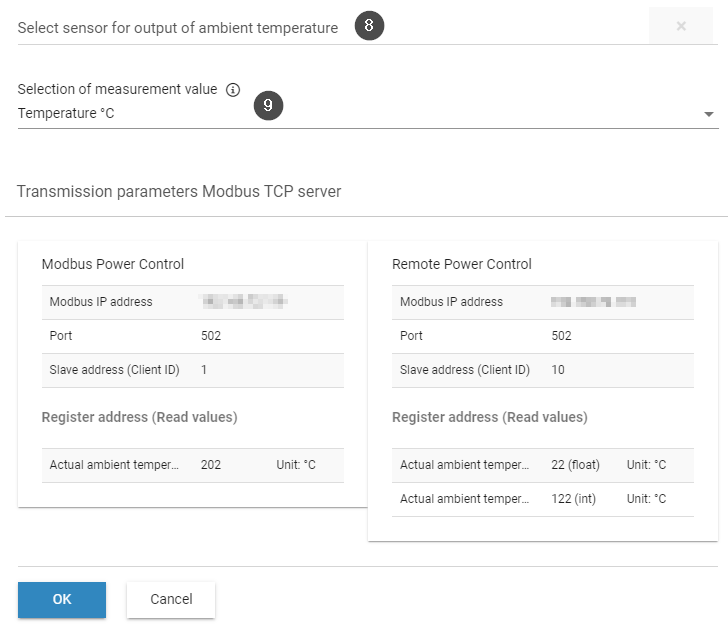
7 | Select sensor for output of ambient temperature | Connect a sensor for a master or slave. The number of sensors will vary depending on the operating mode of the controller (standalone, master, slave). |
8 | Gear icon | Open a window with additional settings for the temperature sensor. |
9 | Selection of measurement value | If a device has multiple temperature sensors, select the measured value to be forwarded via Modbus, e.g. temperature |
Battery plant
You can configure your battery plant's electrical data and characteristics here.
Battery plant
Item | Name | Details |
|---|---|---|
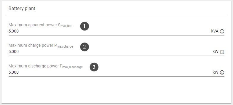
1 | Maximum apparent power Smax,bat | Sum of the maximum AC apparent power of all power generating units within the battery plant |
2 | Maximum charge power Pmax,charge | Sum of the maximum charge active power of all power generating units within the battery plant |
3 | Maximum discharge power Pmax,discharge | Sum of the maximum discharge active power of all power generating units within the battery plant |