Method switch
Last modified:
About method switch
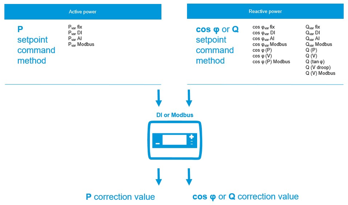
If a grid operator requires more than one setpoint method for active and reactive power control (one method per power type), a mechanism to switch between two or more setpoint methods is needed. This is called a method switch.
To switch between two or more setpoint methods, the grid operator sends a setpoint command, for example, “enable/disable characteristic curve control”. The grid operator may also require an acknowledgment (feedback signal) of the setpoint command. The control loop requires a permanent valid switching command. If the power plant controller (blue’Log XC) does not detect a valid switching command, it switches to fallback behavior (fail-safe operation) after a defined waiting time.
On the blue’Log XC, you can configure a method switch using a digital input (dry contact) or Modbus (network-based method). For an overview of setpoint command methods, see Active power (without Hybrid EMS).
Method switch functional principle
Configure a method switch via digital input
If the method switch is activated via a digital input, you physically wire a control signal to the device. The signal tells the device to switch its operation mode.
Prerequisites
blue’Log XC
Power control is activated
Open-loop or closed-loop control is set
If a variable fixed value such as Pvar Modbus has to be used in either method switch, the Modbus power control license is required. See Modbus Power Control data sheet: Downloads - meteocontrol GmbH
Steps
Navigate to Power control > Active power or Reactive power > Activate the Method switch toggle.
New fields will appear. Select Method switch via digital input (DI) and configure the following optional items.
Pulse group: Here you can specify whether the inputs are switched as pulses or permanently. You can find this information in the manufacturer documentation of the device.
Input (command): Specify the inputs required for control. By default, all digital inputs are listed. If you need fewer inputs, remove them using the
 Trash can icon.
 Acknowledgment: Some network operators require an acknowledgment of the input signals. For this, activate the Acknowledgment toggle. By default, the acknowledgments are output at the digital outputs of the blue'Log. Advanced configuration options are available for this.
Basic method (default method): The controller uses this method until the blue’Log receives the control signal. See Fallback behavior (without Hybrid EMS). Select a method and configure it via the
 Gear icon.
 Select the
 Plus icon to add additional methods.
Examples:
Configure a method switch via Modbus
If the method switch is controlled via Modbus, the blue’Log listens for the setpoint command method from the controller or computer to decide how to operate. For the relevant registers (write values), see the Modbus Power Control data sheet.
Prerequisites
blue’Log XC
Power control is activated
Open-loop or closed-loop control is set
Modbus Power Control license is installed
Steps
Navigate to Power control > Active power or Reactive power > Activate the Method switch toggle.
New fields will appear. Select Method switch via Modbus
Select Information about the interface to view the transmission parameters for the Modbus TCP server.
Select the desired method. Further configurations are required depending on the method you select.
Select the
 Plus icon to add additional methods.
Notes
A method can be selected only once.
If the setpoint command method is not received via Modbus, the blue’Log will switch to fail-safe operation.